7
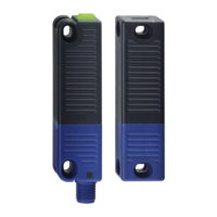
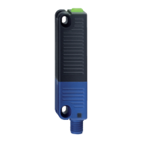
RSS 36
Operating instructions
Safety sensor
EN
6.3 Safety-sensors with serial diagnostic function
(only 8-pin version)
Safety sensors with serial diagnostic cable have a serial input and
output instead of the conventional diagnostic output. If RSS / CSS
safety sensors are wired in series, the safety channels as well as the
inputs and outputs of the diagnostic channels are wired in series.
Max. 31 safety switchgear with serial diagnostics can be wired in
series. For the evaluation of the serial diagnostics line either the
PROFIBUS-Gateway SD-I-DP-V0-2 or the Universal-Gateway SD-
I-U-... are used. This SD-Gateway is integrated as a slave in an existing
field bus system. In this way, the diagnostic signals can be evaluated
by means of a PLC. The necessary software for the integration of the
SD-Gateway is available for download at www.schmersal.net.
The response data and the diagnostic data are automatically and
permanently written in the assigned input byte of the PLC for each
safety sensor in the series-wired chain.
The request data for each safety sensor are transmitted to the device
through an output byte of the PLC.
In the event of a communication error between the SD-Gateway and
the safety sensor, the switching condition of the safety output of the
safety sensor is maintained.
Bit 0: safety outputs enabled
Bit 1: safety sensor actuated, actuator identified
Bit 4: both safety inputs live
Bit 5: safety sensor actuated in hysteresis area
Bit 6: error warning, switch-off delay activated
Bit 7: error, safety outputs switched off
Error
A fault has occurred, which causes the safety outputs to be disabled.
The fault is reset, when the cause is eliminated and bit 7 of the request
byte changes from 1 to 0 or the safety guard is opened. Faults at the
safety outputs are only deleted upon the next release, as the fault
rectification cannot be detected sooner.
Error warning
A fault has occurred, which causes the safety outputs to be disabled
after 30 minutes. The safety outputs initially remain enabled. This
enables the shutdown of the process in a controlled manner. An error
warning is deleted when the error cause is eliminated.
Diagnostic error (warning)
If an error (warning) is signalled in the response byte, detailed fault
information can be read out.
Detailed information about the use of the serial diagnostics can
be found in the operating instructions of the PROFIBUS-Gateway
SD-I-DP-V0-2 and the Universal-Gateway SD-I-U-….
Table 2: Function of the visual diagnostic LEDs, the serial status signals and the safety outputs by means of an example
System condition LEDs Safety outputs
Y1, Y2
Status signals serial diag-
nostic byte Bit n°
green red yellow 7 6 5 4 3 2 1 0
Non-actauted, inputs X1 and X2 enabled On Off Off 0 V 0 0 0 1 0 0 0 0
Actuated, safety outputs enabled Off Off On 24 V 0 0 0 1 0 0 1 1
Actuated in limit area Off Off Flashes (1Hz) 24 V 0 0 1 1 0 0 1 1
Actuated, warning Off On/flashes Off 24 V 0 1 0 1 0 0 1 1
Actuated, fault Off On/flashes Off 0 V 1 1 0 1 0 0 1 0
The shown bit order of the diagnostic byte is an example. A different combination of the operational conditions will lead to a change of the bit order.
Table 3: Tabular overview of status signals, warnings or error messages
Communication directions: Request byte: from the PLC to the local safety sensor
Response byte: from the local safety sensor to the PLC
Warning/error byte: from the local safety sensor to the PLC
Bit n° Request byte Response byte Diagnostic
Error warnings Error messages
Bit 0: — Safety output activated Error output Y1 Error output Y1
Bit 1: — Actuator detected Error output Y2 Error output Y2
Bit 2: — — Cross-wire Y1/Y2 Cross-wire Y1/Y2
Bit 3: — — Temperature too high Temperature too high
Bit 4: — Input condition X1 and X2 — Wrong or defective actuator
Bit 5: — Actuated in limit area Internal device error Internal device error
Bit 6: — Error warning Communication error
between the field bus Gateway
and the safety sensor
—
Bit 7: Error reset Error
(enabling path switched off)
— —
The described condition is reached, when Bit = 1