3
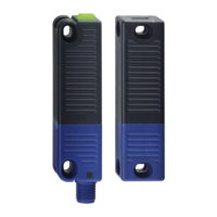
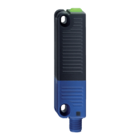
RSS 36
Operating instructions
Safety sensor
EN
Switching distances to IEC 60947-5-3:
Typical switching distance s
typ
: 12 mm
Assured switching distance s
ao
: 10 mm
Assured switch-off distance s
ar
: 20 mm
Hysteresis: < 2.0 mm
Repeat accuracy R: < 0.5 mm
Ambient conditions:
Ambient temperature: −25 °C … +70 °C
Storage and transport temperature: −25 °C … +85 °C
Protection class: IP65 / IP67 / IP69 to IEC 60529
Resistance to vibration: 10 … 55 Hz, Amplitude 1 mm
Resistance to shock: 30 g / 11 ms
Switching frequency f: 1 Hz
Reaction time:
- Actuator: ≤ 100 ms
- Inputs: ≤ 0.5 ms
Duration of risk: ≤ 200 ms
Time to readiness: ≤ 2 s
Electrical data:
Rated operating voltage U
e
: 24 VDC −15% / +10%
(PELV to IEC 60204-1)
Rated operating current I
e
: 0.6 A
Minimum operating current I
m
: 0.5 mA
Required rated short-circuit current: 100 A
Rated insulation voltage U
i
: 32 V
Rated impulse withstand voltage U
imp
: 800 V
No-load current I
o
: 35 mA
Residual current I
r
: < 0.5 mA
Protection class: III
Overvoltage category: III
Degree of pollution: 3
Safety inputs X1/X2:
Rated operating voltage U
e1
: 24 VDC −15% / +10%
(PELV unit)
Current consumption per input: 5 mA
Accepted test pulse duration on input signal: ≤ 1.0 ms
- With test pulse interval of: ≥ 100 ms
Classification: ZVEI CB24I
Sink: C1 Source: C1 C2 C3
Safety outputs Y1/Y2: p-type, short-circuit proof
Operating current I
e1
: max. 0,25 A
Utilisation category: DC-12 U
e
/I
e
24 VDC / 0.25 A
DC-13 U
e
/I
e
24 VDC / 0.25 A
Voltage drop U
d
: U
e
< 1 V
Test pulse duration: ≤ 0.3 ms
Test pulse interval: 1000 ms
Classification: ZVEI CB24I
Source: C2 Sink: C1 C2
Diagnostic output: short-circuit proof, p-type
Operating current I
e2
: max. 0,05 A
Utilisation category: DC-12 U
e
/I
e
24 VDC / 0.05 A
DC-13 U
e
/I
e
24 VDC / 0.05 A
Voltage drop U
d
: U
e
< 2 V
Serial diagnostic: short-circuit proof
Operating current: 150 mA
Wiring capacitance: max. 50 nF
External cable protection: fuse 2.0 A
Max. ambient 69 °C.
This device complies with part 15 of the FCC Rules and
Industry Canada license-exempt RSS standard(s).
Operation is subject to the following two conditions:
(1) This device may not cause harmful interference, and
(2) this device must accept any interference received,
including interference that may cause undesired operation.
Le présent appareil est conforme aux CNR d'Industrie
Canada applicables aux appareils radio exempts de licence.
L'exploitation est autorisée aux deux conditions suivantes:
(1) l'appareil ne doit pas produire de brouillage, et
(2) l'utilisateur de l'appareil doit accepter tout brouillage
radioélectrique subi, même si le brouillage est susceptible
d'en compromettre le fonctionnement.
2.6 Safety classification
Standards: ISO 13849-1, IEC 61508, IEC 62061
PL: e
Control Category: 4
PFH value: 2.7 x 10
-10
/ h
PFD: 2.1 x 10
-5
SIL: suitable for SIL 3 applications
Mission time: 20 years
3. Mounting
3.1 General mounting instructions
Please observe the relevant requirements of the
standards ISO 12100, ISO 14119 and ISO 14120.
Ensure the safety sensor and actuator is mounted on a flat surface.
The universal mounting holes provide for a variable mounting by means
of M4 screws (tightening torque 2.2 … 2.5 Nm).
The component can be mounted in any position. The labelled surfaces
of the safety sensor and the actuator have to be opposite. The safety
sensor must only be used within the assured switching distances
≤ s
ao
and ≥ s
ar
.
The actuator must be permanently fitted to the safety guards
and protected against displacement by suitable measures
(e.g. tamperproof screws, gluing, drilling of the screw heads).
To avoid any interference inherent to this kind of system and any
reduction of the switching distances, please observe the following
guidelines:
• The presence of metal chips in the vicinity of the sensor is liable to
modify the switching distance.
• Keep away from metal chips.
• Minimum distance 100 mm between two safety sensors
as well as other systems with same frequency (125 kHz)
Accessories (to be ordered separately)
Kit tamper-proof screws
• 4 x M4x25 incl. washers, ordering code 101217746
• 4 x M4x30 incl. washers, ordering code 101217747
Sealing kit
• Ordering code 101215048
• 8 plugs and 4 washers
• to seal the mounting holes and as spacer
(approx. 3 mm) to facilitate the cleaning below the mounting surface
• also suitable as tampering protection for the screw fixings.