4
Operating instructions
Safety sensor
RSS 36
EN
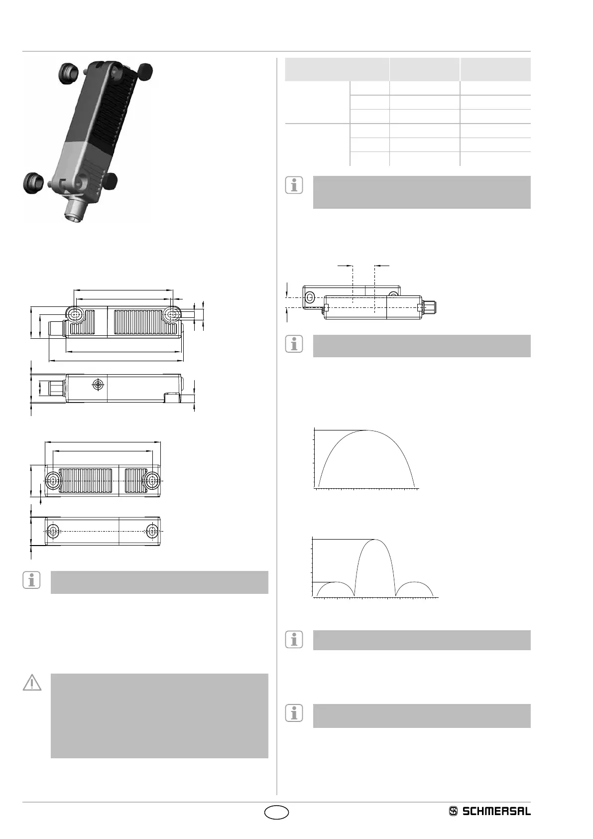
3.2 Dimensions
All measurements in mm.
Safety sensor
106
91
74
78
25
4,5
19
6,5
M12
2
22
0,3
Coding Level: High
V2
Actuator
91
78
2522 0,3
0,3
V2
Alternative suitable actuators with different design:
refer to www.schmersal.net.
3.3 Switch distance
Switching distances to IEC 60947-5-3:
Typical switching distance s
typ
: 12 mm
Assured switching distance s
ao
: 10 mm
Assured switch-off distance s
ar
: 20 mm
There are new switch distances as per the table below
owing to the necessity of technical modifications (V2).
Please check the design of your guard system following
installation to ensure adherence to the secured switch
distances (≤ s
ao
and ≥ s
ar
) in accordance with the specified
values and adjust the guard system accordingly.
The positions of the designations V2 should be gleaned
from the dimensional drawings under 3.2.
Switching distances in
mm to IEC 60947-5-3
Actuator
RST
Actuator
RST V2
Sensor
RSS
s
typ
12 12
s
ao
10 8
s
ar
16 16
Sensor
RSS V2
s
typ
12 12
s
ao
10 10
s
ar
20 20
With the combination of "old sensor – new actuator (V2)" there
may be limitations in availability owing to the reduced s
ao
(8 mm). This change has no affect on the performance level.
The side allows for a maximum height misalignment (X) of sensor
and actuator of ± 8 mm (e.g. mounting tolerance or due to guard door
sagging). The axial misalignment (y) is max. ± 18 mm.
X
Latching versions X ± 5 mm, Y ± 3 mm.
The latching force will be reduced by misalignment.
Actuating curves
The actuating curves represent the typical switching distance of
the safety sensor during the approach of the actuator subject to the
actuating direction
Transverse misalignment
-5-20 51015-15 20-10 0
0
5
10
Height misalignment
-5-20-24 51015-15 20
-10 0
0
5
10
12
Preferred actuation directions: from front or from side.
3.4 Adjustment
The continuous signal of the yellow LED signals the actuator detection;
the flashing of the yellow LED signals that the safety sensor is actuated
in the hysteresis area.
Recommended Adjustment
Align the safety sensor and actuator at a distance of 0.5 x s
ao
.
The correct functionality of both safety channels must be checked by
means of the connected safety-monitoring module.