9
RSS 36
Operating instructions
Safety sensor
EN
9.2 Wiring examples
The application examples shown are suggestions. They however do not release the user from carefully checking whether the switchgear and its
set-up are suitable for the individual application.
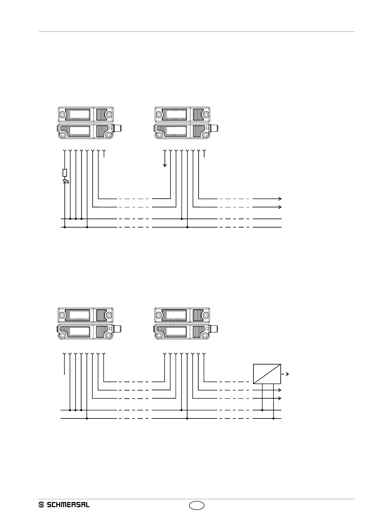
Wiring example 1:
Series-wiring of the RSS 36 with conventional diagnostic output
The voltage is supplied to both safety inputs of the last safety sensor of the chain (considered from the safety-monitoring module). The safety
outputs of the first safety sensor are wired to the safety-monitoring module. The diagnostic output can be connected for instance to a PLC.
X1
Y1
X2
Y2
12356 8
X1
X2
A1
A2
Y1
Y2
12356 8
X1
4
Y1
4
Y1
X2
7
Y2
7
Y2
OUT
A1
A2
OUT
SPS/PLC
24 VDC
RST 36
RSS 36
RST 36
RSS 36
Y1 and Y2 = Safety outputs -> Safety-monitoring module
Wiring example 2:
Series-wiring of the RSS 36 with serial diagnostic function
The voltage is supplied to both safety inputs of the last safety sensor of the chain (considered from the safety-monitoring module).
The safety outputs of the first safety sensor are wired to the safety-monitoring module. The serial Diagnostic Gateway is connected to the serial
diagnostic input of the first safety sensor.
1235468
X1
Y1
X2
SD IN
SD OUT
A1
A2
1235468
X1
Y1
X2
7
Y2
7
Y2
SD IN
SD OUT
A1
A2
X1
Y1
X2
Y2
SD INSD OUT
Y1
Y2
SD IN
RST 36
RSS 36
RST 36
RSS 36
Y1 and Y2 = Safety outputs -> Safety-monitoring module
SD-IN -> Gateway -> Field bus