5
SRB-E-212ST / SRB-E-322ST
Operating instructions
Safety-monitoring module
EN
5. Operating principle and settings
5.1 Description of the terminals and LED indications
Pin Function LED Function
A1 Operating voltage
+ 24DVC
RUN Operating voltage OK
RUN mode
For flash code, see
section 5.3
A2 Operating voltage
0 V
ERR Error code
refer to part 5.5
X2 Input of start circuit
X3 Input
feedback circuit
X7 Input
Release signal
S11/S21 Test pulse outputs
S12 Input channel 1 In 1 High level at S12
For flash code, see
section 5.4
S22 Input channel 2 In 2 High level at S22
For flash code, see
section 5.4
Y1 Signalling output
(NC) STOP 0
Y2 Signalling output
(NC) STOP 1
41/42 Signalling contact
(NC) STOP 0
13/14,
23/24,
33/34
Safety outputs
STOP 0
Out 1 Outputs activated
For flash code, see
section 5.4
Qt1/Qt2 Safety outputs
STOP 1
Out 2 Outputs activated
For flash code, see
section 5.4
1
0
S11 S1 2 S2 1 S22
A1A2X3X2
X7Qt1Y2Y1
SRB-E-212ST
2 42 31 413
Out 2
time[s]
RUN
ERR
ln 1
ln 2
Out 1
mode
1
0
S11 S1 2 S2 1 S22
A1A2X3X2
Qt2Qt1X7Y2
SRB-E-322ST
2 42 31 413
4 24 13 433
time[s]
RUN
ERR
ln 1
ln 2
Out 1
Out 2
mode
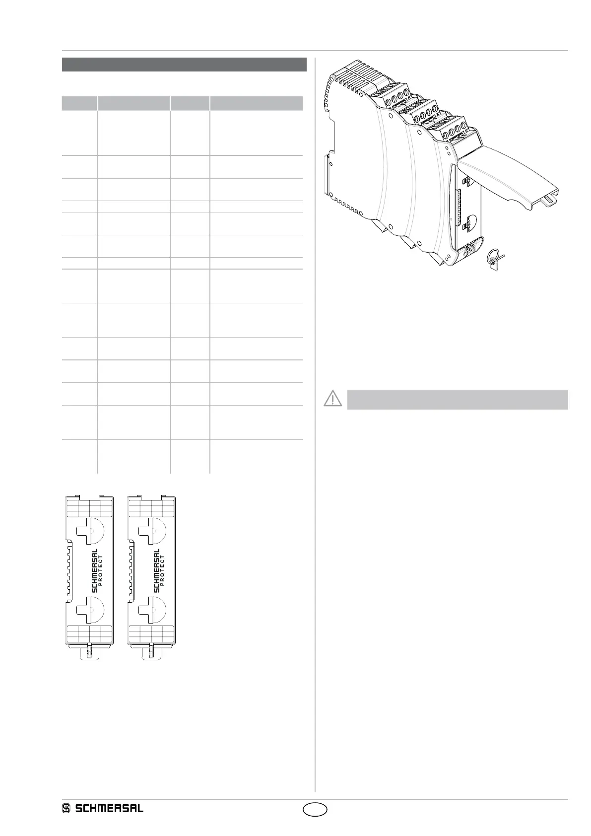
Adjustment of application using rotary “mode” switch
• Open front transparent cover (see fig.).
• Opening is carried out by lifting side with lock.
• Select desired application using rotary mode switch (1 … 10)
by turning up or down (see 5.3).
• Adjust drop-out delay (0 … 30 sec.) with rotary time switch
(16 increments) by turning up or down (see 5.3).
• After performing setting, close front cover again.
• Front cover can be secured with a lead seal to protect it from being
opened unintentionally
Only touch the components after electrical discharge!
 Loading...