9
SRB-E-212ST / SRB-E-322ST
Operating instructions
Safety-monitoring module
EN
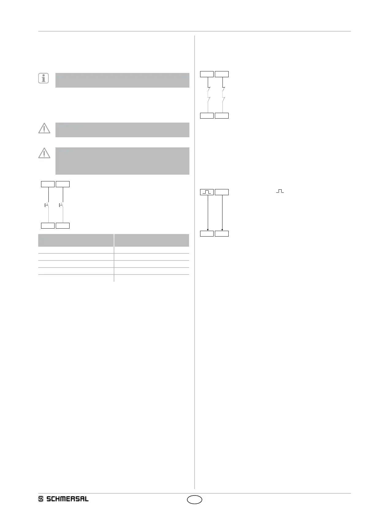
7.3 Start configuration
7.3.1 External reset button
• Manual start or activation of the module occurs when the button
is released (detection of the trailing edge).
Monitoring of max. actuation time 0.03 sec. … 3 sec.
If the time is exceeded, the module cannot be started!
7.3.2 Reset without monitoring / autostart
• The manual start or the activation of the module occurs when the
button is pressed (not when it is released!).
• With autostart, X2 must be bridged to S11, S21 or +24 VDC
Not admitted without additional measure due to the risk of
gaining access by stepping behind!
Within the meaning of EN 60204-1 paragraph 9.2.5.4.2,
the operating mode "automatic start" is only restrictedly
admissible. In particular, any inadvertent restart of the
machine must be prevented by other suitable measures.
X2
J
S11/S21
X2
+24 VDC
J
Reset button (detection of the
trailing edge)
Reset without monitoring /
autostart
Rotary knob position 1 Rotary knob position 6
Rotary knob position 2 Rotary knob position 7
Rotary knob position 3 Rotary knob position 8
Rotary knob position 4 Rotary knob position 9
Rotary knob position 5 Rotary knob position 10
7.4 Feedback circuit / Release signal
• Suitable for increase in capacity or number of contacts by means of
contactors or relays with positive-guided contacts. If the feedback
circuit is not required, establish a bridge.
X3
S11/S21
X3
+24 VDC
K
B
K
A
K
B
K
A
• The safety contacts and outputs can be switched during operation via
the safety input X7 with the guard system closed.
• The safety outputs Qt1 and Qt2 are not switched off until the set delay
time has elapsed.
• For safety-orientated use, a fault in the wiring (short circuit to 24 V
potential) must be able to be excluded!
• If no deactivation during operation is required, this input must be
switched to + 24 VDC.
X7 X7
+24 VDC
= control signal
 Loading...