Copyright © 2021 Axxiom Manufacturing, Inc.
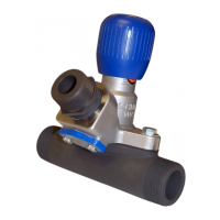
5.8.2. Electric Deadman System: When the electric deadman lever (#12) is pressed down it
closes the electric circuit and supplies electric current to the control valve (#20). The
control valve opens and sends air signals to the ComboValve® (#4) to begin blasting.
When the deadman lever is released, the electric circuit is turned off closing the control
valve. The signal air vents from the breather (#35) and the ComboValve closes to stop
blasting. See Figure 5.4, Figure 5.5, and the drawing in Section 9.3.
Electric shock hazard. Abrasive blasters with electric deadman blast control systems
must operate on low voltage supply (12-24 volts). To minimize shock hazard only use
low voltage sources and use caution when connecting the power to the abrasive blaster.
See Section 3.7.
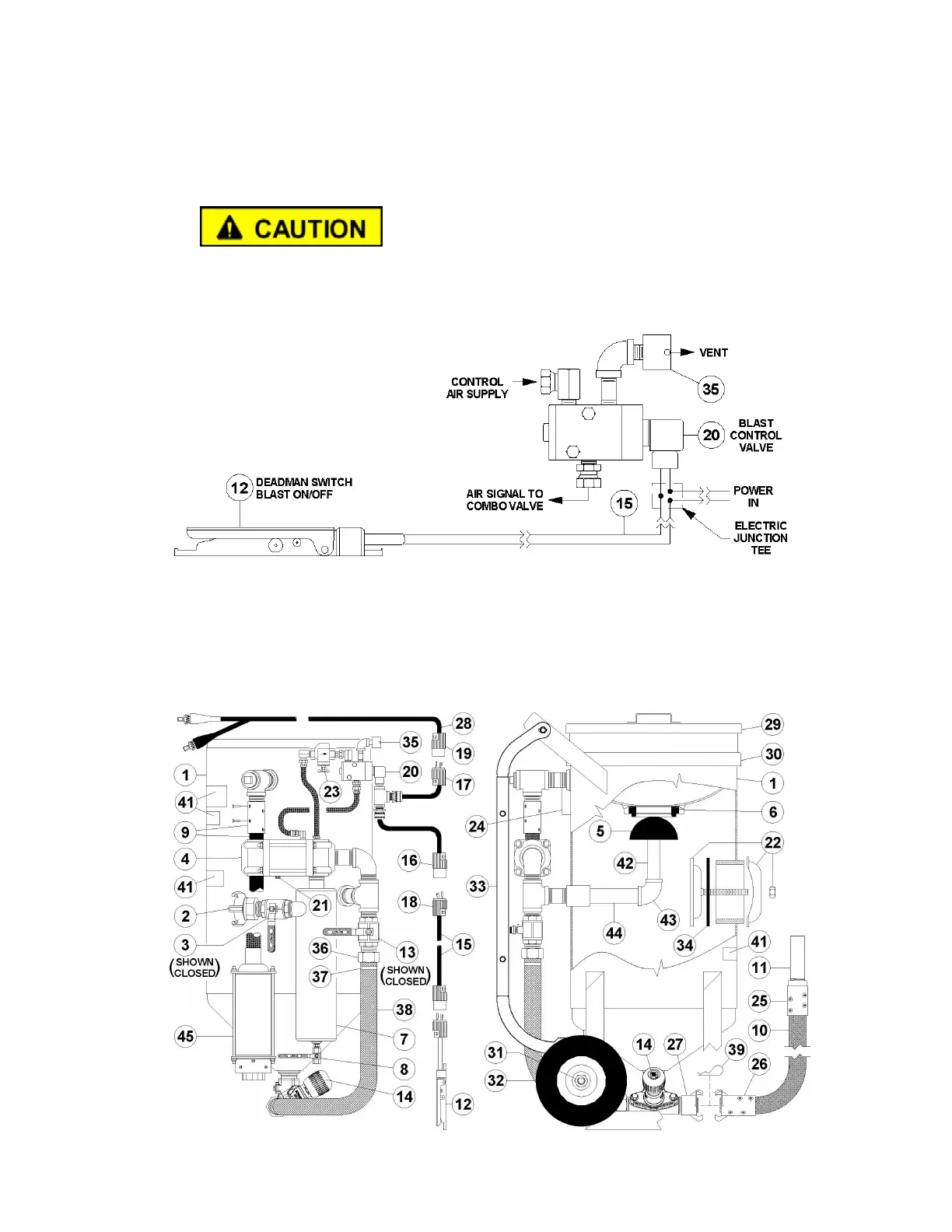
Figure 5.4 – MV3 Valve Electric Deadman Blast Control System
5.9 MV3 Valve Abrasive Blaster with Electric Control System
Figure 5.5 shows a MV3 Valve abrasive blaster with the electric deadman system. The popup
valve, MV3 Valve, and ComboValve operate the same as a blaster with a pneumatic blast
control system. The difference is that the electric control system uses an electric control valve
(#20) operated by the electric deadman switch as detailed in Section 5.8.2.
Figure 5.5 – MV3 Valve Abrasive Blaster with electric blast controls