Copyright © 2021 Axxiom Manufacturing, Inc.
5.10 Blast Hose
The blast air and abrasive mixture flows from the MV3 Valve (#14) to the blast nozzle (#11)
through the blast hose assembly (#10). The typical length of the blast hose is 50ft; however,
blast hose extensions can be added to increase length. For higher efficiency keep the blast hose
as short as possible. Increased blast hose length causes pressure drop at the blast nozzle which
reduces the blast efficiency. For higher efficiency use a blast hose with an inside diameter that
is approximately three times the nozzle throat diameter. Keep blast hose as straight as possible.
Sharp bends create high wear points. Static electricity is generated by the abrasive flow through
the blast hose. To minimize chance of static electrical shock to operating personnel only use
anti-static blast hose and/or vacuum hose, properly electrically bond the blast nozzle, blast hose
couplings, and the equipment, and properly install an earth ground to the abrasive blaster.
Static electric shock hazard. To minimize chance of static electrical shock to operating
personnel only use anti-static blast hose, properly electrically bond the blast nozzle, blast hose
couplings, and the equipment, and properly install an earth ground to the abrasive blaster.
Note: To reduce operator fatigue a blast whip hose can be used along with the blast hose. A
whip hose is thinner wall and lighter weight hose. Consult an Authorized Schmidt® distributor.
5.11 Blast Nozzle
The blast nozzle (#11) is an important part of the blast operation since the size of it determines
the air flow and abrasive requirement. The amount of air flow and abrasive determine how
quick blasting can be done. The larger the nozzle, the more air and abrasive will be needed. The
larger the nozzle size the greater the blast productivity. However, for a fixed amount of air
supply, increasing the nozzle size will reduce the blast pressure. For best performance, the blast
pressure must be maintained as high as possible. Therefore, select the nozzle size based on the
amount of air available and then adjust the abrasive flow at the MV3 Valve as needed.
The nozzle size can be identified by the small number molded into the outer nozzle jacket. Or in
the case of ceramic nozzles, by measuring the throat diameter (the smallest inside diameter).
The throat diameter is measured in sixteenths of an inch; for example, a #5 nozzle has a throat
diameter of 5/16". See the tables in Section 13.0 for approximate air and abrasive consumption
for each nozzle. Note: For the best possible mixture of air to abrasive, the blast hose and piping
must be at least three times the size of the blast nozzle.
5.12 Hose Connection
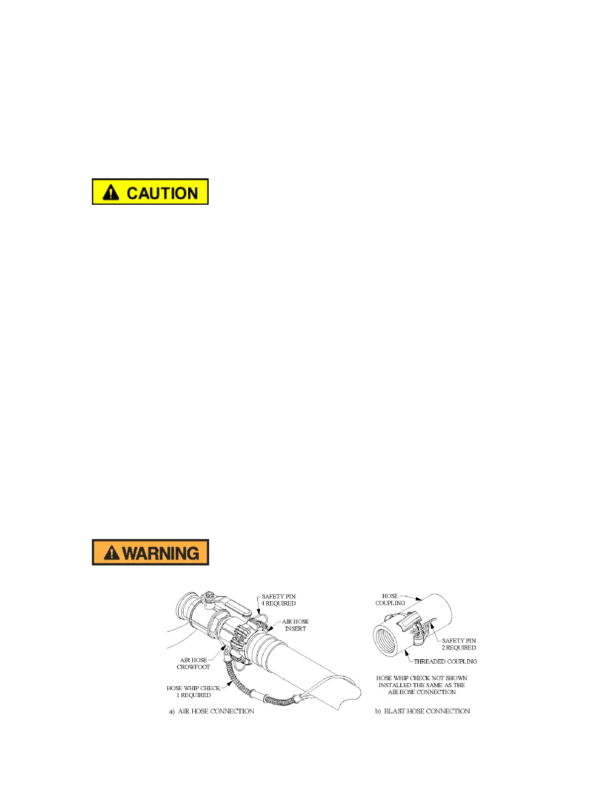
All air hose, blast hose, and threaded couplings have two pin holes that align when connected.
To protect against accidental hose disconnections safety pins must be installed through these
holes. As a secondary safety measure each hose connection should also include a hose whip
check that will hold the hose if there is an accidental disconnection. Connect one loop to each
side of the connection and stretch out as shown in Figure 5.6 below. All air hose, blast hose,
and threaded couplings have a gasket that seals the connection and should be replaced when air
is leaking.
Failure to install safety pins on all air and blast hose couplings can result in hose disconnects
and could result in serious injury or death.
Figure 5.6 – Hose Connection Disconnect Protection