Copyright
This manual remains the copyrighted property of SCHUNK GmbH & Co. KG. It
is solely supplied to our customers and operators of our products and forms
part of the product. This documentation may not be duplicated or made ac-
cessible to third parties, in particular competitive companies, without our
prior permission.
Technical changes
We reserve the right to make alterations for the purpose of technical im-
provement.
Document number:1005274
Edition:01.00|23/01/2017|de - en
© SCHUNK GmbH & Co. KG
All rights reserved.
1Intended use
If the gripper finger has some clearance, if the positioning is incorrect or if
movement is asymmetrical, the gripper finger will need to be changed. Ex-
pansion cracks or enlargement of the guide groove are the most frequent
indicators of a defective gripper finger. The cause for this defect is often a
collision. After a collision, the piston rod may also be damaged.
2Scope of Delivery
Designation GWB
34 44 54 64 80
Gripper fingers [pcs.] 1 1 1 1 1
Set-screw [pcs.] 2 2 2 2 2
Cylindrical pin [pcs.] 1 1 1 1 1
Switching lug [pcs.] 1 1 1 1 1
Designation GWB
34 44 54 64 80
Bracket for NHS [pcs.] 1 1 1 1 1
Screw [pcs.] 1 1 1 1 2
3Applicable documents
• Catalog data sheet of the product *
• Assembly and operating manual of the product *
The documents marked with an asterisk (*) can be downloaded on our
homepage www.schunk.com.
4Notes on particular risks
WARNING
Risk of injury due to sudden movements!
If the energy supply is switched on or if residual energy is still present in the
system, this can cause components to move unexpectedly, which may res-
ult in serious injuries.
• Switch off energy supply and secure against re-connection.
• Ensure that no residual energy remains in the system.
5Tools/auxiliary tools
• Hexagon socket wrench
• Drift punch
• Hammer
6Recommended lubricants
not required
7Tightening torque
not required
8Threadlocker
If not stated otherwise, screws can be secured using Loctite 243 or a similar
adhesive.
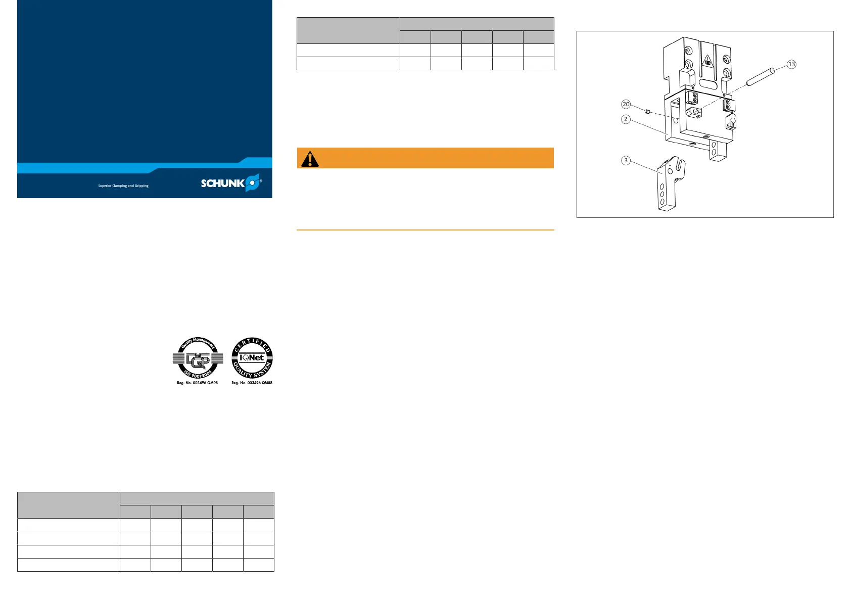
9Changing the gripper finger
Dismantling
Ø Remove all compressed air lines.
Ø Disassemble gripper from the machine/automated system.
Ø Connect compressed air line to the gripper and put gripper finger (3) into
"opened" position.
Ø Unscrew set-screw (20) from the gripper finger (3).
Ø Push cylinder pin (13) out of the housing (2).
Ø Remove the gripper finger (3) from the housing (2).
Assembly
When assembling, use the parts from the spare part package.
Ø Clean all parts thoroughly, check for damage and wear.
Ø Insert the gripper finger (3) into the housing (2).
Ø NOTICE!Make sure the installation position of the cylinder pin (13) is
correct.
Insert the cylinder pin (13) into the housing (2) in such a way that the
groove is over the bore hole for the set-screw (20).
Ø Screw the set-screw (20) into the gripper finger (3).
Ø Remove the compressed air line.
Ø Assemble gripper on the machine/automated system.
Ø Secure all compressed air lines.
GWB34-80
Gripper finger spare parts
package
Repair Instructions
SCHUNK GmbH & Co. KG | Spann- und Greiftechnik
D-74348 Lauffen/Neckar | Bahnhofstr. 106 – 134
Tel. +49-7133-103-0 | Fax +49-7133-103-2399
info@de.schunk.com | www.schunk.com
 Loading...