_______________________________________________________________________________________
schunk.com XND.00046.002_A – 08/2022 7
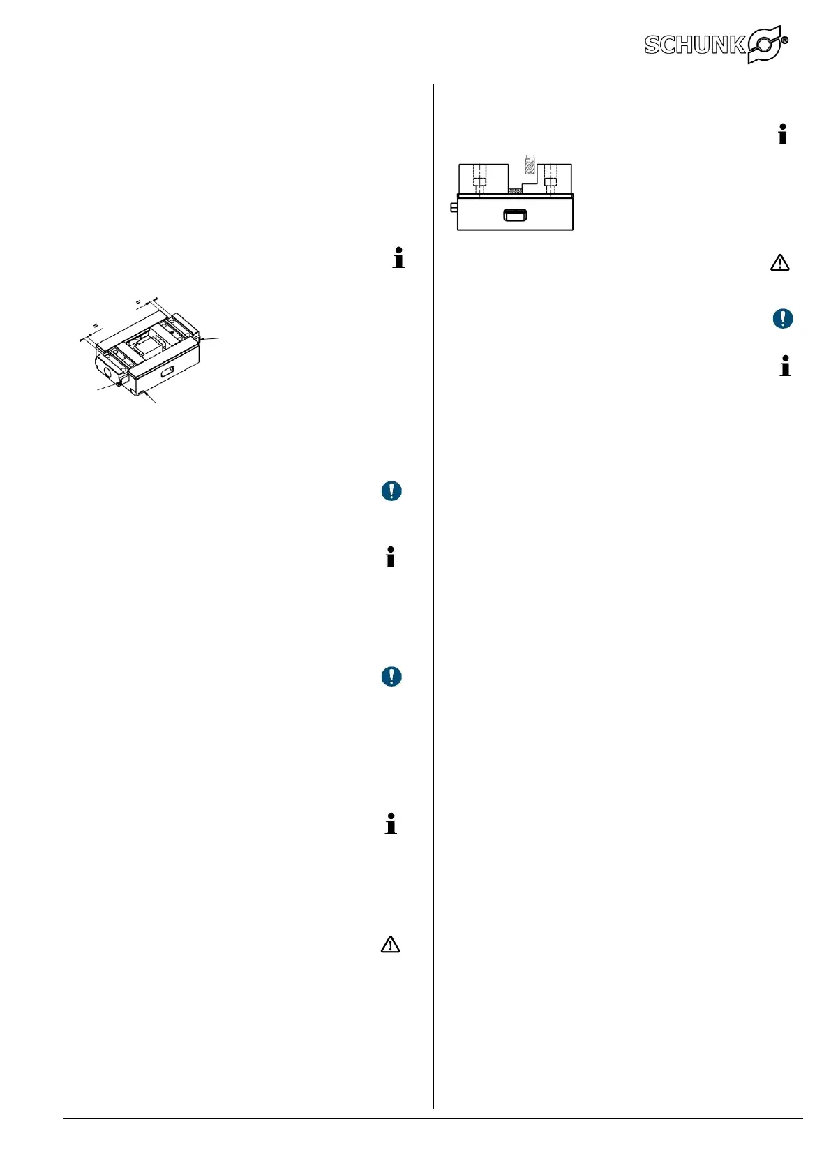
6.2 Installation
Clean the system completely.
Re-grease the thread of the spindle and at the carriages using e.g. EP high-performance
grease, such as LAGERMEISTER WHS 2002, NLGI class 1-2.
Oil the running surfaces and bearing of the vise using e.g. with MOTOREX Supergliss 68 K to
ISO VG 68.
Insert both carriages into the base plate up to the thread beginnings of the spindle.
Important:
Both carriages and the base plate must have the identical serial number.
Screw in the threads by turning the spindle clockwise and pressing on both carriages ends
at the same time.
Important:
Both carriages must come together and engage in the threads at the same time. This is
imperative in order to ensure the consistent central position of the system.
Checking the central position
The gap between the carriage slot and the end face of the base plate must be
identical on both sides. If this is not the case, remove the carriages again and repeat
the process.
Finally, fully join the carriages together so that the inside wipers on the vises
KSC3 125-235, KSC3 125-300 and KSC3 160 are again pressed into the carriages via the
spacer O-rings.
If present, refit end stops.
Important:
The high degree of precision of the KSC3 is achieved using a processing step while it
is mounted.
The components of different vises must not be interchanged.
Both carriages and the base plate must have the identical serial number.
This is imperative in order to ensure the consistent central position of the system and the
fitting of the guide between the carriages and base plate.
Swivel and adapter plate 7
OP10: Clamping with grip clamping steps of 3, 8 or 18 mm.
OP20: Clamping on tungsten carbide coated side. When clamping
the system jaws may yield slightly. The workpiece position must
be measured.
7.1 Fitting the swivel and adapter plate
KSC3 125-160 and KSC3 160: Depending on the selected mounting position of the swivel
plate or the mounting positions of the 6-fold turning jaws, a centric workpiece position in
relation to the base plate symmetry is possible.
KSC3 80, KSC3 125-235 and KSC3 125-300: The workpieces are clamped asymmetrically to
the base plate.
For reasons of stability, the swivel plate with the bearing journal must not be
inserted in the outermost sliding groove.
7.2 Fitting the 6-fold reversible jaws
Determine the mounting positions of the 6-fold reversible jaws. The best clamping results are
achieved when clamping parts as far out as possible.
Move the cover screws so that the selected clamping position is available.
Position the 6-fold reversible jaws and loosely insert the cylinder screws.
Turn the 6-fold reversible jaws on to the required clamping faces and slightly
Pre-clamp the workpiece so that the clamping faces are parallel to, and touch,
the workpiece.
Use a torque of 80 Nm to tighten the cylinder screws of the 6-fold reversible jaws.
Important:
When the clamping faces of the 6-fold reversible jaws are not aligned parallel to the
workpiece surface it is possible that the 6-fold reversible jaw becomes loose through the
clamping force.
7.3 Troubleshooting, eliminating faults
Swivel plate is difficult to turn
Disconnect the swivel plate and push the swivel peg from below out of the swivel plate.
Check the vise guide and swivel plate surface for indentations or deformations.
If necessary, re-grind the plate and the vise guide.
Check the peg for soiling.
Check that the O-rings are correctly positioned. The upper O-ring must make good contact.
Lubricate the entire system with grease and reassemble.
When handling, the swivel plate should not be turned upside down.
Aluminium jaws 8
The aluminium jaws are designed for producing workpiece-specific clamping contours. In
order to achieve maximum precision of the contour, it is recommended that the contour
milling is carried out with pre-clamping of the aluminium jaws. For this purpose, a
narrow spacer piece can be clamped at the bottom and the pre-clamped aluminium jaws
can then be milled to achieve the desired clamping contour.
Important:
Mill the system jaw to a maximum depth of the screw head.
Ensure that the clamping cross-section is sufficient.
Service / Maintenance 9
Note:
It is not possible to supply spare parts for the carriage, base plate and spindle, as these
are designed and fitted at the factory to work together.
Repairs can be carried out by the manufacturer or an authorised service agent.
Taking out of service 10
The clamping device and all accessories can be disposed of as scrap metal without any
risk.
 Loading...