Start-up
03.00 | MEG 50 EC | Assembly and Operating Manual | en | 389201
31
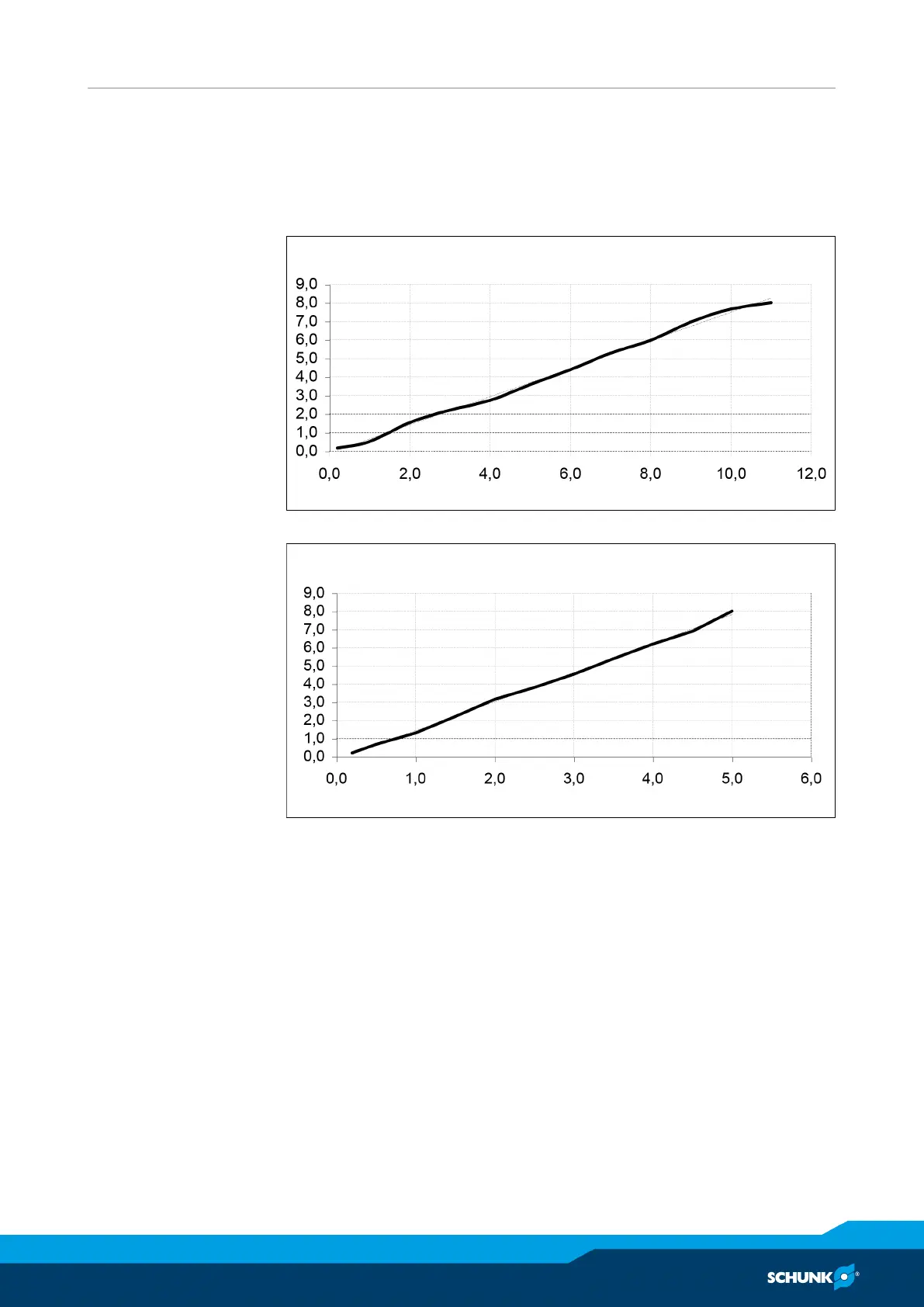
The following diagram shows the relative traverse path when the
input voltage is specified at the analog input "Steps" (terminal 23).
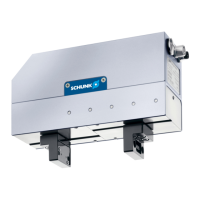
The next diagram shows the relative traverse path when the
voltage is specified via the "Pos." potentiometer (potentiometer
P3) on the controller MEG C.
Travel preset = f[input voltage] via external input
Travel
in mm
y = 0,7613x - 0,1186
Input voltage in V
relative traverse path when the analog voltage is specified on (terminal 23)
Travel preset = f[input voltage] on potentiometer
y = 1,5995x - 0,1792
Travel
in mm
Input voltage in V
relative traverse path when the analog voltage is specified via potentiometer
"Pos." (P3)