Relay Element Settings 2-25
SEL-300G Instruction Manual Date Code 20020206
DWG: M300G045
+
-
24D1D
0
Volts/Hertz Element
Curve Timing and
Reset Timing
Settings
24D2P1 24ITD
24D2D1 24D2P2
24IP 24D2D2
24IC
24D1
24D1T
24C2
24C2T
24CR
(V/Hz)
t
V/Hz
24D2P1
24D2P2
24IP
24D2D2
24CCS=DD
24IP
24D2P2
t
V/Hz
24CCS=ID
Relay
Word
Bits
24TC
Switch
closed
when
24TC=1
24D2D2
24CCS
V/Hz
t
24CCS=I
24D2D1
24TC
SEL
OGIC
Setting
24D1P
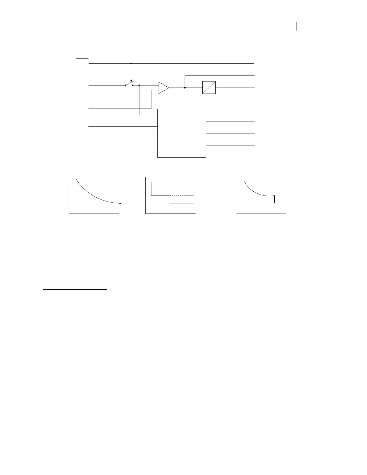
Figure 2.13: Volts/Hertz Element Logic Diagram
REVERSE/LOW-FORWARD POWER ELEMENT
Element Description
Functional Description
Generator motoring occurs when prime mover input power to the generator is cut off while the
generator is connected to the system. When this happens, the generator acts as a synchronous
motor to drive the prime mover shaft. In steam turbine prime mover applications, generator
motoring can quickly damage the turbine by causing overheating. In applications of other prime
movers, motoring can cause mechanical damage and/or unsafe operating conditions.
Antimotoring protection in the SEL-300G Relay is provided by a reverse/low-forward power
element. This element measures the real-power flow from the generator. If the generator
real-power output drops below the element threshold, the relay asserts the Relay Word bit
associated with the instantaneous threshold and starts the element definite timer.
Two reverse-power thresholds are provided. The threshold settings are made in per unit of rated
generator power. One per unit generator power is defined by the VNOM and INOM relay
settings. If two steps of reverse-power tripping are not required, you may elect to apply one



 To Next Page