SEL-787-2, -3, -4 Data Sheet Schweitzer Engineering Laboratories, Inc.
30
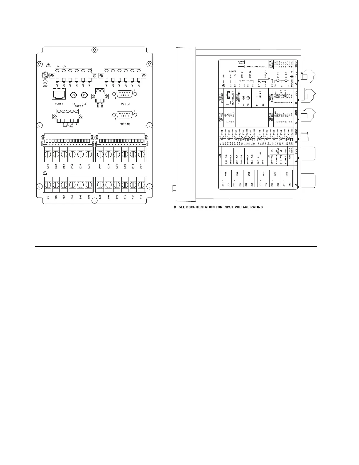
SEL-787-2E Rear and Side Panels
(A) Rear-Panel Layout (B) Side-Panel Layout
Figure 44 SEL-787-2E With Single Ethernet, EIA-232/EIA-485 Communications, and RTD Option
Applications
The SEL-787 is designed to provide differential and
overcurrent protection for power transformers, generator
step-up transformers, and autotransformers with as many
as four windings/terminals. In addition, the SEL-787
contains advanced integration and control features that
will allow its application in a wide variety of automation
and control schemes. Refer to Section 2: Installation and
Section 4: Protection and Logic Functions of the instruc-
tion manual for more details.
Figure 45 shows the application of an SEL-787-4X
Relay for protection of a three-winding transformer. You
can configure Windings 1, 2, and 4 on the relay for
differential protection, and you can apply the 50/51
elements associated with each winding towards
overcurrent protection. You can configure A-phase and
B-phase of Winding 3 on the relay for REF protection for
Windings 1 and 2, respectively. You can configure
C-phase of Winding 3, along with the RTD thermal
elements, to provide fan bank control and protection. Use
additional RTD thermal elements to monitor LTC tank
temperatures and SEL
OGIC programming to indicate
temperature differential alarms between transformer and
LTC tank temperatures.
Figure 46 shows an SEL-787-3E Relay protecting an
autotransformer with three terminals. You can configure
Windings 1, 2, and 3 on the relay for differential
protection, and you can apply the 50/51 elements
associated with each winding towards overcurrent
protection. You can configure Channel IN on the relay
for REF protection. You can use the three-phase voltage
inputs for V/Hz, over- and undervoltage, over- and
underfrequency, and directional power protection.
Apply the transformer through-fault monitoring of the
SEL-787 to keep track of accumulated through-fault I
2
t
values. Monitor the number of through faults,
accumulated I
2
t, and fault duration times to determine
the frequency (through-fault events per day, week,
month, or year) and impact of external faults on the
transformer.
 Loading...


