Step 1
Step 2
Step 3
Step 4
Steps 1 & 2
Step 2c
Inspect the incline adjuster assembly
Tools Required: Estimated Time to Complete: Service Manual Procedure:
Phillips head screwdriver
6mm hex key/Allen wrench
13mm, 19mm open-ended wrench
5 to 10 minutes Replace the Incline (Lift) Motor
Access the incline motor
Important: Unplug the power cord from both the front of your machine and the electrical
outlet before continuing
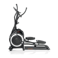
1. Before we can remove the shroud to access the incline motor, we will need to
disconnect the incline motor arm from the rail assembly:
a. To prevent risk of serious injury, do not place your hands or fingers below any
pivoting parts on the rail assembly.
b. There are four nuts and bolts securing the incline motor arm to the rail
assembly.
c. On each fastener, use a 13mm open-ended wrench to stabilize the nut and a
6mm Allen wrench to loosen and remove the bolt.
d. Once all bolts have been removed, the incline motor arm and rail assembly will
separate, and the front of the rail assembly will rest on the floor.
e. Slide the incline motor arm from the rail assembly.
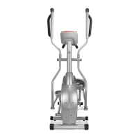
2. Use a Phillips head screwdriver to loosen and remove the four screws (two on each
side) attaching the rear shroud:
One screw is located near the crank arm.
One screw is located near the handlebar pivot joint.
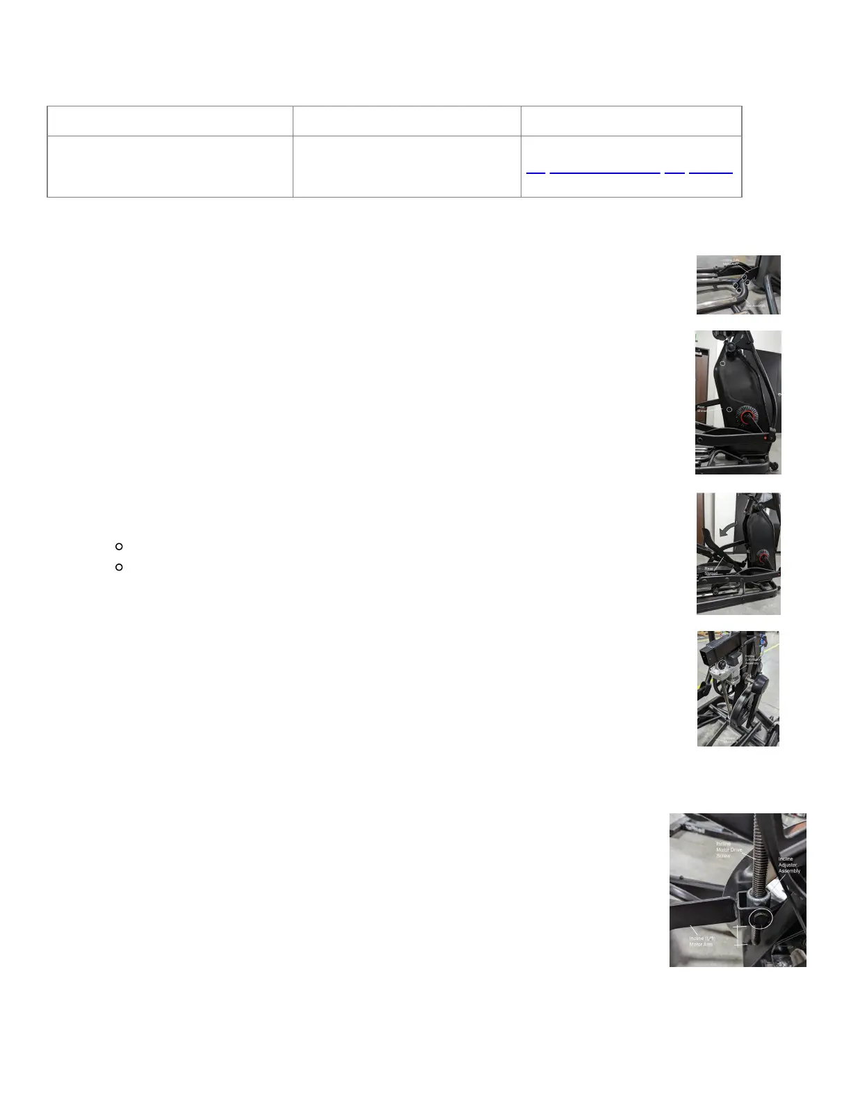
3. Gently pivot the rear shroud down along the incline motor arm. Slip the shroud
between the incline motor arm and the rail assembly (where we removed the four
bolts in Step 1), then set it to the side for reassembly later.
4. The incline motor is located inside the rear shroud access we just created, mounted
to the frame of your elliptical near the drive pulley.
Check the incline adjuster assembly
1. The incline adjuster assembly is located at the bottom of the drive screw
and connects the incline motor arm to the incline motor.
2. If the incline adjuster assembly is not attached, the incline motor arm cannot move
when the incline is adjusted. To reattach the incline adjuster assembly:
a. Use a 19mm open-ended wrench to loosen and remove the hex head bolts
from the incline adjuster assembly.
b. Reinstall the incline adjuster assembly by rotating it onto the bottom of the
drive screw.
c. Adjust the position of the incline adjuster assembly so that it is approximately
15mm to 20mm from the motor housing at the top of the drive screw - this is
equal to about two to three exposed drive screw threads.
d. We will use a 19mm open-ended wrench again to tighten the hex head bolts
and secure the incline adjuster assembly to the drive screw.
 Loading...