12| 3.0 Initial Setup
4. Place the slave stage on the opposite side of your microscope to
the motorised stage. Remove the shipping bracket from the
inside edge of the slave stage – nearest the microscope. Leave
the outside edge shipping bracket in place.
5. Place the top plate across the two stages, aligning the larger,
untapped holes in the surface with those on the two stages.
Insert two M6x12 screws into mounting holes in opposite
corners of each stage to temporarily hold the structure.
6. Adjust the position of the assembly into the optimum mounting
position on the anti-vibration table. Ensure the sample plate is
always within the optical axis of the microscope and there is
room for 25 mm travel in every direction.
7. Remove the final shipping bracket from the slave stage,
accessing it under the side of the top plate. Keep this to hand as
it will be required again in later stages of this process.
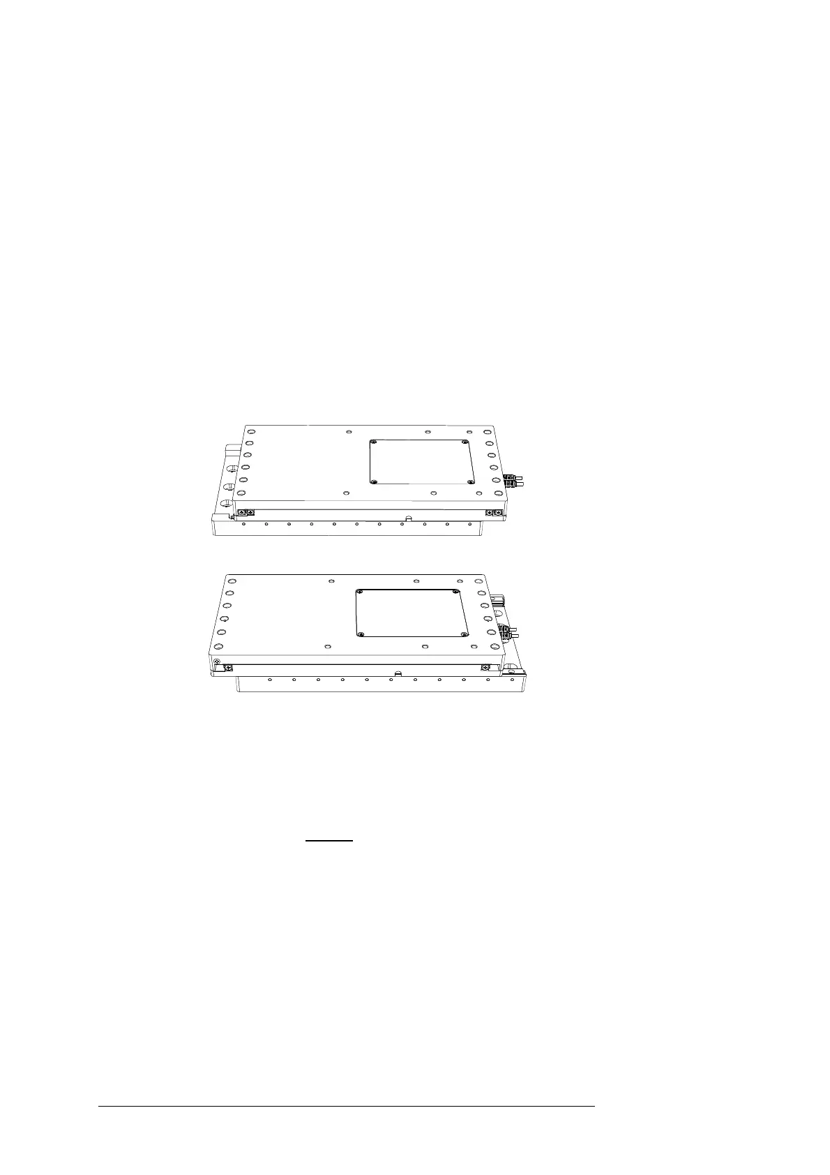
FRONT REAR
B
A
F
igure: Stage mounting holes
(A)Shown driven to the rear to reveal the front mounting holes,
and (B)driven to the front to reveal the rear mounting holes.
8. Using the control device, drive the assembly backwards to reveal
the front mounting holes on the lower front edge of both stages.
Using M6x12 screws, loosely bolt down the stages at front – the
mounting holes should be accessible under the front of the top
plate. You may need to adjust the assembly to align with the
tapped holes on the anti-vibration table.
9. Using the control device, zero the axes of both stages. Re-fit the
outer shipping bracket on the slave stage and then remove the
top plate.
10. Using the control device, drive the motorised stage forwards to
reveal the additional mounting holes at the rear of the stage.
Using M6x12 screws, firmly secure the stage. Drive the stage to
the back again and fully tighten the front screws. Once mounted,
return the motorised stage to its zero position.