152
SCION xA (EM00D0U)
Air Conditioning
Current is applied at all times through the HTR fuse to TERMINAL 5 of the HTR relay.
When the ignition SW is turned on, the current flows through the GAUGE fuse to TERMINAL 1 of the HTR relay to
TERMINAL 2 to TERMINAL 6 of the blower SW.
Blower Motor Operation
∗ Low speed operation
When the blower SW is moved to LO position, the current flows to TERMINAL 2 of the blower SW to TERMINAL 1 to
GROUND, causing the HTR relay to turn on. This causes the current flows from the HTR fuse to TERMINAL 5 of the
HTR relay to TERMINAL 3 to TERMINAL 1 of the blower motor to TERMINAL 2 to TERMINAL 1 of the blower resistor to
TERMINAL 4 to GROUND, rotating the blower motor at low speed.
∗ Medium speed operation (Operation at M1, M2)
When the blower SW is moved to M1 position, the current flows to TERMINAL 2 of the blower SW to TERMINAL 1 to
GROUND, causing the HTR relay to turn on. This causes the current flows from the FR HTR fuse to TERMINAL 5 of the
HTR relay to TERMINAL 3 to TERMINAL 1 of the blower motor to TERMINAL 2 to TERMINAL 1 of the blower resistor to
TERMINAL 2 to TERMINAL 7 of the blower SW to TERMINAL 5 to GROUND. At this time, the blower resistance of the
blower resistor is smaller than at low speed, so the blower motor rotates at medium low speed.
When the blower SW is moved to M2 position, the current flows through the HTR relay to TERMINAL 1 of the blower
motor to TERMINAL 2 to TERMINAL 1 of the blower resistor to TERMINAL 3 to TERMINAL 6 of the blower SW to
TERMINAL 1 to GROUND. At this time, resistance of the blower resistor is smaller than at M1 position, so the blower
motor rotates at medium high speed.
∗ High speed operation
When the blower SW is moved to HI position, the current flows to TERMINAL 2 of the blower SW to TERMINAL 1 to
GROUND, causing the HTR relay to turn on.
This causes the current flows from the HTR fuse to TERMINAL 5 of the HTR relay to TERMINAL 3 to TERMINAL 1 of
the blower motor to TERMINAL 2 to TERMINAL 10 of the blower SW to TERMINAL 1 to GROUND, rotating the blower
motor at high speed.
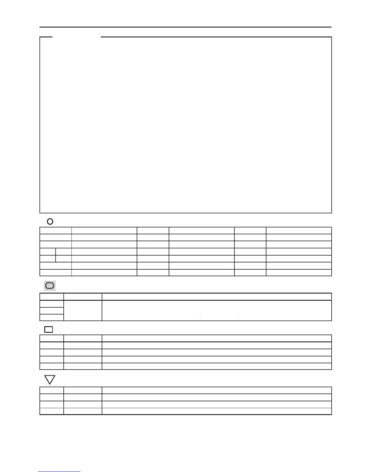
: Parts Location
Code See Page Code See Page Code See Page
A2 28 B4 30 J2 31
A7 30 C5 30 J7 31
A17 A 30 C7 30 J8 31
A18 B 30 E5 30 J10 31
A19 28 F12 30
B3 30 I12 31
Connector Joining Wire Harness and Wire Harness
Code See Page Joining Wire Harness and Wire Harness (Connector Location)
EB1 34 Engine Wire and Engine Room Main Wire (Inside of the Engine Room R/B)
ID3 36 Engine Room Main Wire and Instrument Panel Wire (Upper Side of the Instrument Panel J/B)
IF2 37 Engine Wire and Instrument Panel Wire (Left Side of the Blower Unit)
IG1 37 Instrument Panel Wire and A/C Sub Wire (Right Kick Panel)

 Loading...