108
SCION xA (EM00D0U)
ABS without VSC
This system controls the respective brake fluid pressures acting on the brake cylinders of the right front wheel, left front
wheel, and rear wheels when the brakes are applied in a panic stop so that the wheels do not lock.
This results in improved directional stability and steerability during panic braking.
1. Input Signal
(1) Speed sensor signal
The speed of the wheels is detected and input to TERMINALS FL+, FR+, RL+ and RR+ of the skid control actuator with
ECU.
(2) Stop light SW signal
A signal is input to TERMINAL STP of the skid control actuator with ECU when the brake pedal is depressed.
2. System Operation
During sudden braking, the skid control actuator with ECU which has signals input from each sensor lets the hydraulic
pressure acting on each wheel cylinder escape to the reservoir.
The pump inside the skid control actuator with ECU is also operating at this time and it returns the brake fluid from the
reservoir to the master cylinder, thus preventing locking of vehicle wheels.
If the skid control actuator with ECU judges that the hydraulic pressure acting on the wheel cylinder is insufficient, the current
acting on the solenoid is controlled and the hydraulic pressure is increased.
Holding of the hydraulic pressure is also controlled by the ECU, by the same method as above, by repeated pressure
reduction. Holding and increase are repeated to maintain vehicle stability and to improve steerability during sudden braking.
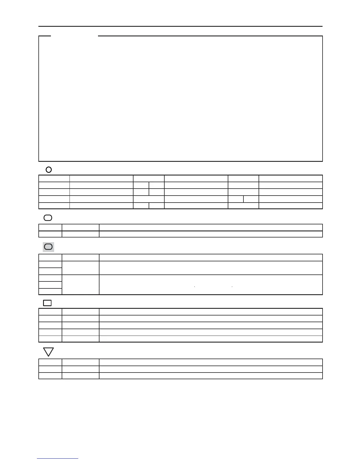
: Parts Location
Code See Page Code See Page Code See Page
A3 28 C10 A 30 I10 31
A4 28 C11 B 30 P4 31
A15 32 D1 30 S1 B 29
A16 32 F10 B 28 S6 31
Connector Joining Wire Harness and Wire Harness
Code See Page Joining Wire Harness and Wire Harness (Connector Location)
IC1 36 Engine Room Main Wire and Floor Wire (Left Side of the Cowl Panel)
ID2 36 Engine Room Main Wire and Instrument Panel Wire (Upper Side of the Instrument Panel J/B)
BC1 38 Skid Control Sensor Rear LH Wire and Floor Wire (Front Side of the Quarter Wheel House Inner Panel LH)
BD1 38 Skid Control Sensor Rear RH Wire and Floor Wire (Front Side of the Quarter Wheel House Inner Panel RH)
Ground Points
Code See Page Ground Points Location
ED 34 Front Fender Apron LH
IF 36 Instrument Panel Brace LH
System Outline

 Loading...