Boston Electronics Corporation, 91 Boylston Street, Brookline MA 02445
(800)347-5445 or (617)566-3821 * fax (617)731-0935 * boselec@boselec.com * www.boselec.com
Bartles Industrial Estate, North Street, Redruth, Cornwall TR15 1HR
Tel. (01209) 314608 E-mail: scitec@scitec.uk.com
Fax. (01209) 314609 Web: http://www.scitec.uk.com
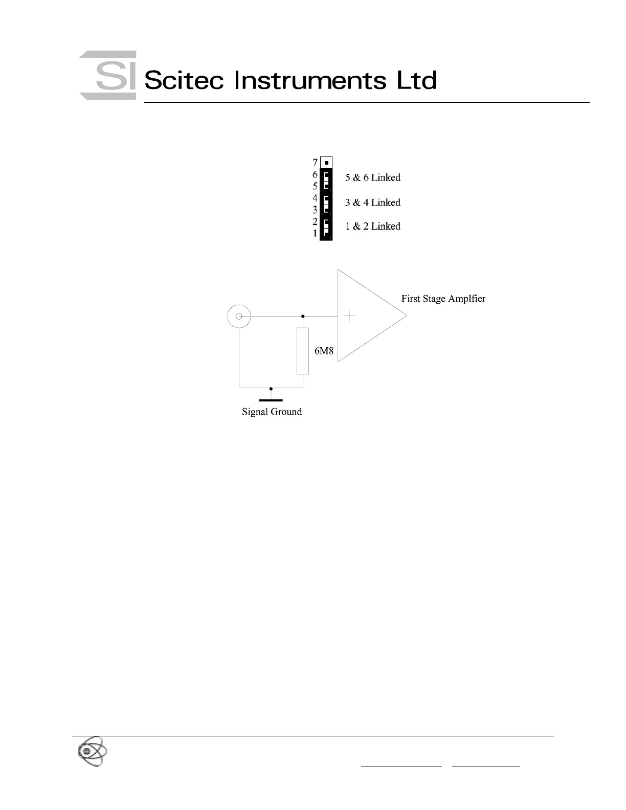
Figure 7 Single Ended Current Input Settings
Figure 8 Single Ended Current Input Circuit
3.6 Differential Input
The above 3 modes can all be converted to a differential input by removing the link between
pins 5 and 6.
It is useful to place the unit into differential mode if you do not wish the input signal ground to
be connected to the lock-in amplifier signal ground. This can be done to break a ground loop or
other such problem.
For example the jumper settings for the Differential DC coupled input are shown in Figure 9
and the equivalent circuit is shown in Figure 10. The other modes are similar.
Please note that it is important that the input signals are not left to float when in differential
mode but are externally coupled to ground by some method. If this is not done, the DC offset
on the input will rise (or fall) until the levels specified in section 3.3 are breached. The input
signal will then be distorted as it travels through the input stage and you will get an erroneous
result.