Boston Electronics Corporation, 91 Boylston Street, Brookline MA 02445
(800)347-5445 or (617)566-3821 * fax (617)731-0935 * boselec@boselec.com * www.boselec.com
Bartles Industrial Estate, North Street, Redruth, Cornwall TR15 1HR
Tel. (01209) 314608 E-mail: scitec@scitec.uk.com
Fax. (01209) 314609 Web: http://www.scitec.uk.com
4 SIGNAL GROUND, CASE GROUND AND EARTH
For safety reasons the metal case that houses the lock-in amplifier is permanently connected to
electrical earth via the power connector. No modifications should be made to this connection as
otherwise it may be possible for the case to become live under fault conditions.
The signal ground used within the instrument can however be isolated safely from the case
ground and earth.
The signal ground is the signal ground mentioned in section 3 and is the ground connection
made to the reference BNC (12) and the output BNC (8).
Three different methods of connection are possible and are selected by jumpers within the unit.
4.1 Accessing Input Stage Jumpers
The input stage includes jumpers which enable the mode of operation of the input stage to be
modified. To access the jumpers:
(1) Switch off and disconnect power before opening unit.
(2) Remove the 10 screws holding the lid on then remove lid. Do not disconnect earth strap.
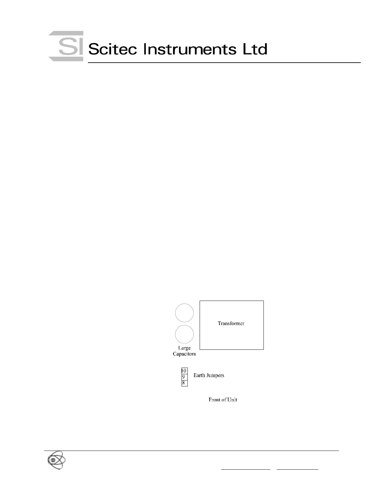
(3) Change the jumper settings as per the diagrams in the following sections. The location of
the earth jumpers are shown in Figure 13. Do not operate the unit with the lid removed due
to the power voltages accessible within the unit.
(4) Replace lid and the 10 screws.
Figure 13 Location of Earth Jumpers
4.2 Signal Ground Connected to Case and Electrical Earth (Default Setting)
The signal ground and hence the ground connection for the reference BNC and output BNC
can be connected directly to the case ground and electrical earth by placing the jumper as
shown in Figure 14.