Boston Electronics Corporation, 91 Boylston Street, Brookline MA 02445
(800)347-5445 or (617)566-3821 * fax (617)731-0935 * boselec@boselec.com * www.boselec.com
Bartles Industrial Estate, North Street, Redruth, Cornwall TR15 1HR
Tel. (01209) 314608 E-mail: scitec@scitec.uk.com
Fax. (01209) 314609 Web: http://www.scitec.uk.com
10 HOW TO MAKE AMPLITUDE AND PHASE MEASUREMENTS
USING AN OSCILLOSCOPE
Amplitude an phase measurements of an input signal can be easily made using the 420 lock-in
and an oscilloscope set to X-Y mode using the following procedure:
(1) Switch the oscilloscope to X-Y mode. Set the gain on both channels to the same setting.
Zero both channels so that the spot is centred on the screen.
(2) Set both the reference phase shift controls (9)(10) to zero.
(3) Connect the X output from the back of the 420 lock-in to the X channel of the oscilloscope.
(4) Connect the Y output from the back of the 420 lock-in to the Y channel of the oscilloscope.
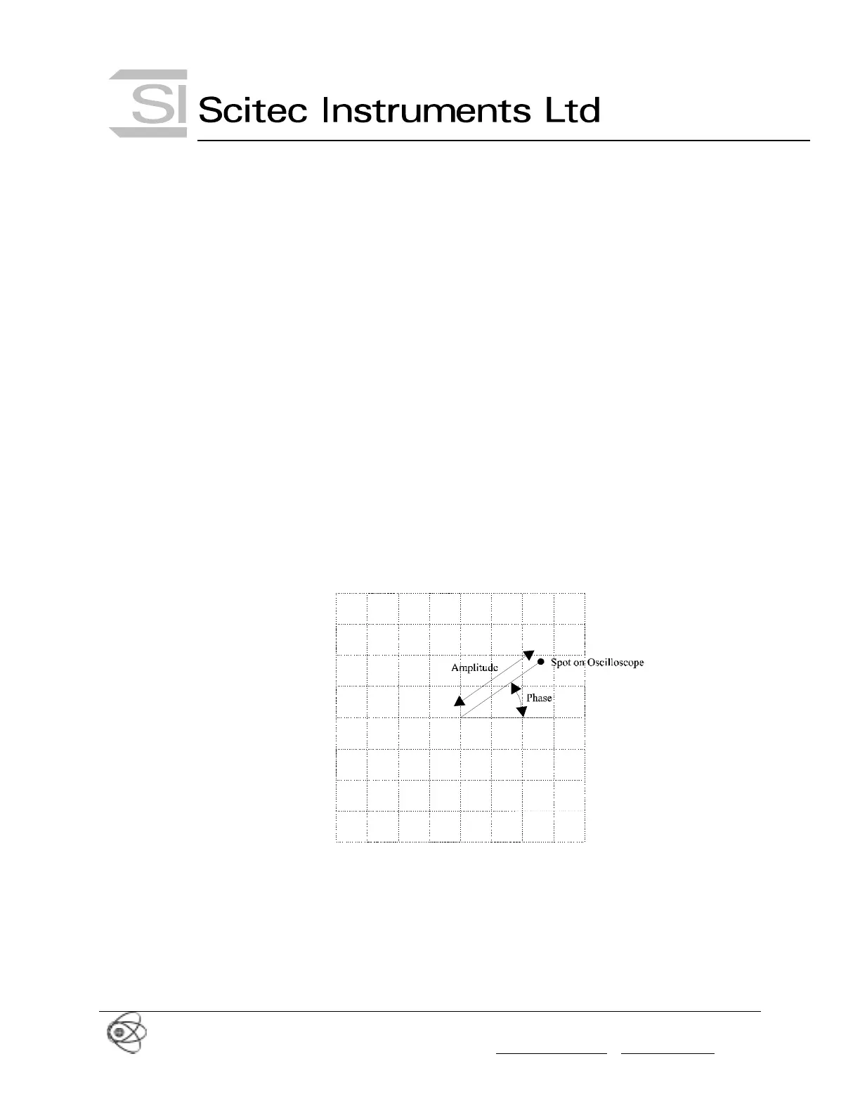
The oscilloscope is now set up to display the input signal as a phaser diagram. See Figure 17.
(5) The amplitude of the input signal can now be measured as it is proportional to the distance
from the centre of the screen to the displayed dot.
(6) The phase of the input signal relative to the reference signal can be measured as being the
angle between the line from the centre of the screen to the displayed dot and the horizontal.
Figure 17 Phaser Diagram on Oscilloscope