Boston Electronics Corporation, 91 Boylston Street, Brookline MA 02445
(800)347-5445 or (617)566-3821 * fax (617)731-0935 * boselec@boselec.com * www.boselec.com
Bartles Industrial Estate, North Street, Redruth, Cornwall TR15 1HR
Tel. (01209) 314608 E-mail: scitec@scitec.uk.com
Fax. (01209) 314609 Web: http://www.scitec.uk.com
this resistor from their measurements. However, how often do you make measurements with
the input shorted in real life??)
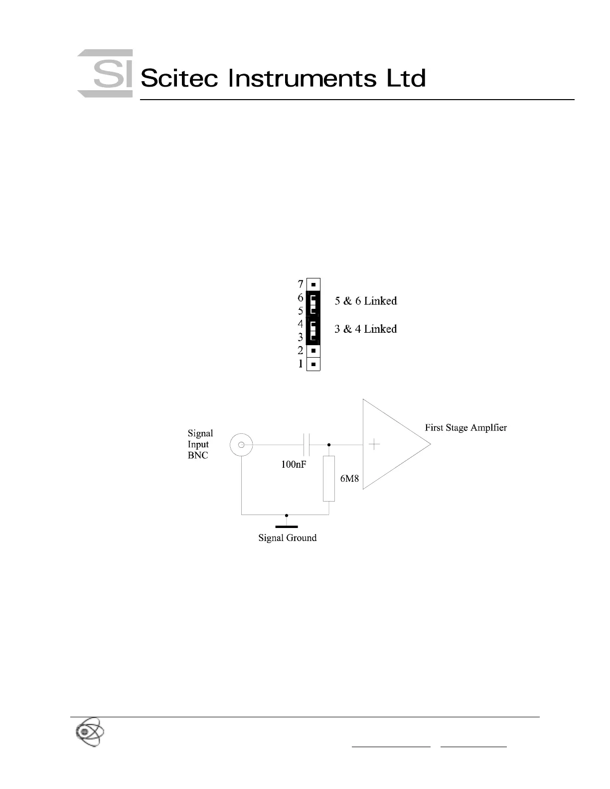
In this mode of operation the input can have up to ±12V DC offset before saturation occurs on
all input gain settings.
The input impedance of the lock-in in this mode is 6.8x10
6
Ω ||100nF.
The jumper settings for this mode is given in Figure 5. The equivalent circuit is shown in
Figure 6.
Figure 5 Single Ended AC Coupled Settings
Figure 6 Single Ended AC Coupled Circuit
3.5 Single Ended Current Input
The input stage can also used as a current input due to the high impedance of the input stage
opamps. The current input is converted to a voltage by the 6.8MΩ resistor which has a
tolerance of 1%. This mode of operation has not been full characterised by Scitec Instruments
and is not guaranteed.
The input impedance of the lock-in in this mode is 6.8x10
6
Ω ||1nF.
The jumper settings for this mode is given in Figure 7. The equivalent circuit is shown in
Figure 8.