Boston Electronics Corporation, 91 Boylston Street, Brookline MA 02445
(800)347-5445 or (617)566-3821 * fax (617)731-0935 * boselec@boselec.com * www.boselec.com
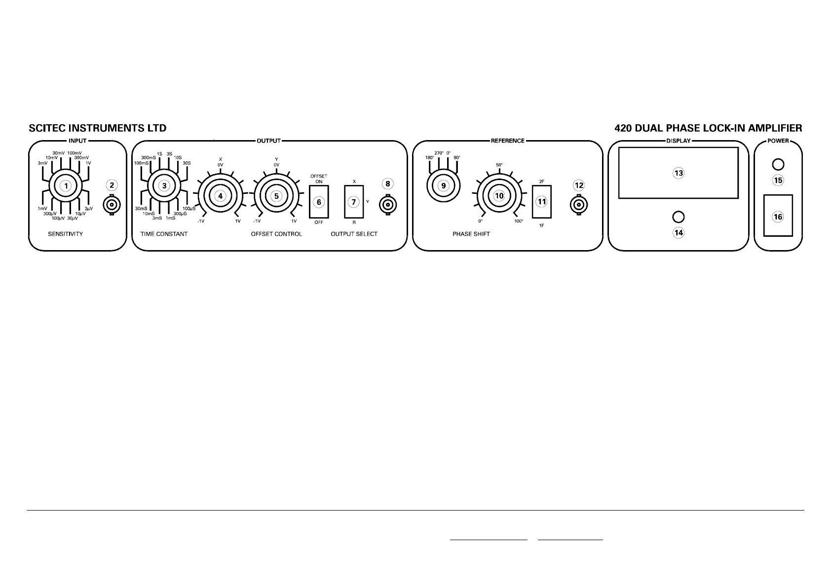
420 FRONT PANEL LAYOUT
Figure 18 - 420 Front Panel Layout
(1) Input Sensitivity Control
Note: It is not possible to rotate the dial directly from 1V
to 3µV.
(2) BNC Signal Input Connection
Note: Overload protection circuitry begins to come into
operation from ±15V.
(3) Output Time Constant Control
Note: It is not possible to rotate the dial directly from 30S
to 100µS.
(4) X Output Offset Control
Note: This dial only comes into operation when the output
offset switch is set to on.
(5) Y Output Offset Control
Note: This dial only comes into operation when the output
offset switch is set to on.
(6) Output Offset On/Off Switch
Enables or disables the output offset control dials.
(7) Output Select Switch
Selects value output on BNC connection and that shown
on the display
(8) BNC Output Connection
(9) Coarse (90°) Phase Control
(10) Fine Phase Control
(11) 1F/2F Reference Select
Note: With the switch set to 1F the recovered signal is of
the same frequency as the reference signal. With the
switch set to 2F the recover signal is twice the
frequency of the reference signal.
(12) BNC Reference Signal Input Connection
Note: Overload protection circuitry begins to come into
operation from ±15V.
(13) Output Meter Display
(14) Output Meter Zero Adjust
(15) Power On Indicator
(16) Power On/Off Switch