Page 21
Page 21
Freeze Cycle
NOTE. Before charging the refrigerant system
always check the type of refrigerant and
quantity as specified on the individual ice
machine dataplate.
The refrigerant charges indicated are related
to average operating conditions.
COMPONENTS DESCRIPTION
A. EVAPORATOR TEMPERATURE
SENSOR
The evaporator temperature sensor probe,
located in contact with the evaporator serpentine,
detects the dropping of the evaporator tempera-
ture during the freezing cycle and signals it by
supplying a current flow to the micro processor of
P.C. BOARD.
According to the current received, the evaporator
sensor supplies power to the P.C. BOARD first,
when it reachs 0°C (32°F), second at -15°C (5°F);
in this second case it supply power to the electronic
timer built into the P.C. BOARD so that it may take
control of the fength of the 2nd phase of freezing
cycle.
The length of the timed phase is pre-f ixed by the
setting of the keys 1, 2, 3 and 4 of the DIP
SWITCH.
The activation of the electronic timer (-15°C -
5°F) is monitored by the lighting up of the RED
LED placed in the front of the P.C. BOARD. This
lighting up occures usually in the mid period of
the freezing cycle and signals the switching
from the first to the second phase of the freezing
cycle.
NOTE. Whenever, after 15 minutes from the
beginning of the freezing cycle, the
evaporating temperature have not yet
reached the value of 0
°
C (32
°
F), the P.C.
BOARD switches OFF the machine with the
BLINKING of RED LED.
B. CONDENSER TEMPERATURE
SENSOR
The condenser temperature sensor probe,
located within the condenser fins (air cooled
version) or in contact with the tube coil (water
cooled version) detects the condenser tempera-
ture variations and signals them by supplying
current, at low voltage, to the P.C. BOARD.
In the air cooled versions, in relation to the
different current received, the micro processor
of the P.C. BOARD supplies, through a TRIAC,
the power at high voltage to the fan motor so to
cool the condenser and to reduce its temperatu-
re.
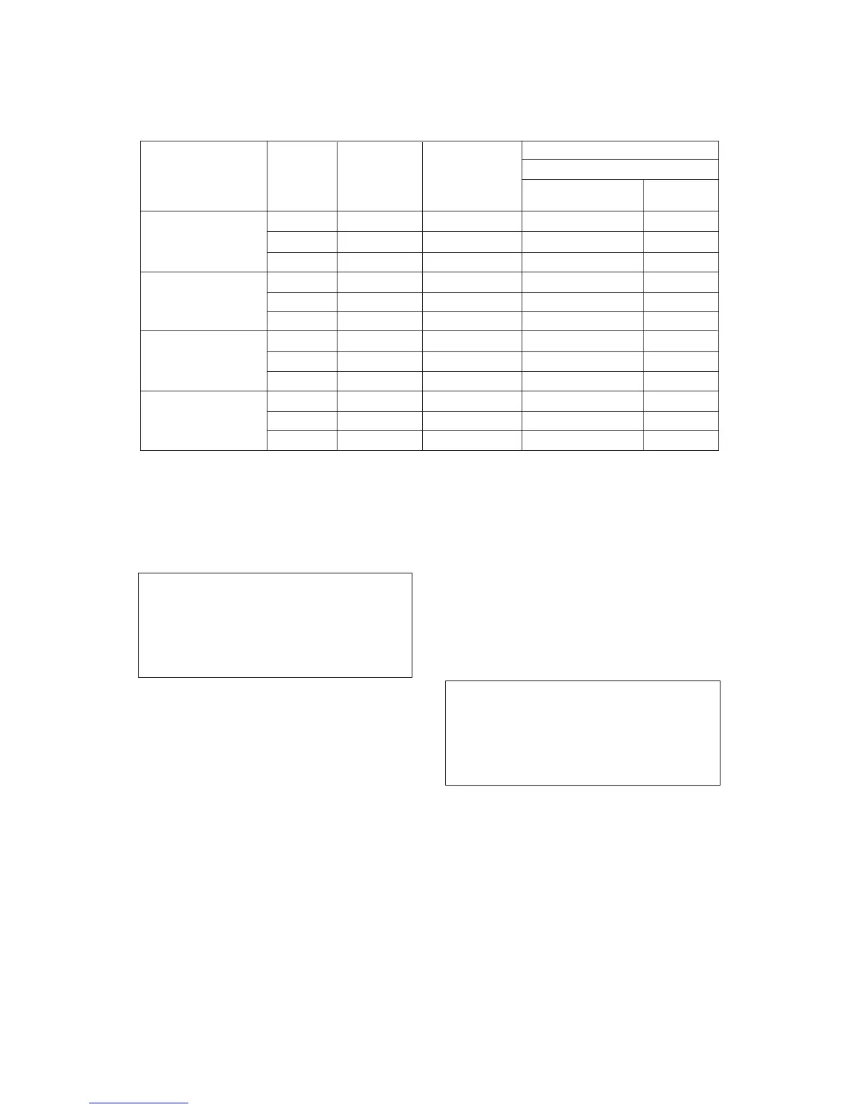
MODEL VOLTAGE CUBE SIZE
discharge
S
MXG 327 A 230/50/1 M 145 2,8 / 1 10 - 13,5
L
S
MXG 327 W 230/50/1 M
L
S
MXG 427-437 A 230/50/1 M 150 1,9 / 0,7 10 - 12
L
S
MXG 427-437 W 230/50/1 M
L
OPERATING PRESSURE
(bar)
at 21°C amb. / 15°C water
suction
(beg./end freez.)
REF. CHARGE
(R290 - gr.)