R1387 DCM2461/SCRIGNO - OPEN2.0 | pagina 61
Open 2.0
EN
Turn o the board, adjust the dip-switches and wait 5 seconds.
Turn the board on again.
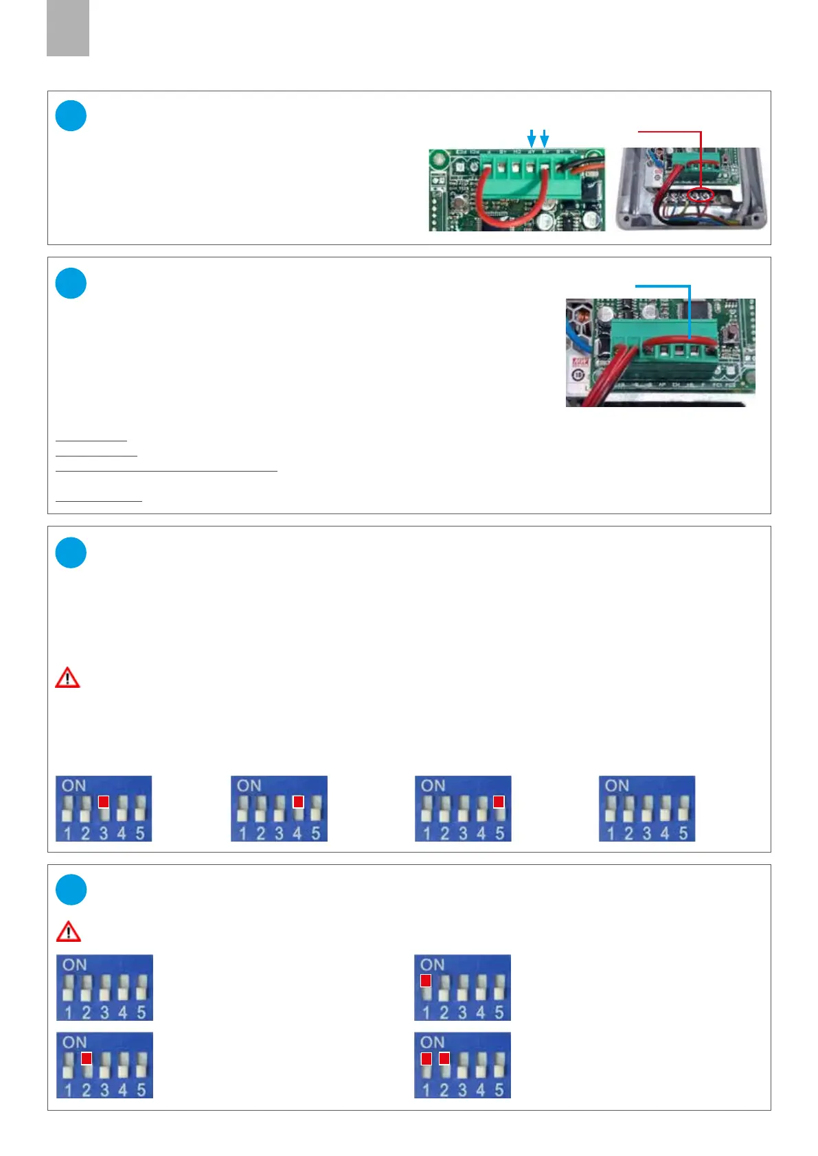
ADJUSTMENT OF THE DOOR-WEIGHT PRESET
DIP SWITCH 3= ON
Preset 1:
Doors weighting
approx. 20 kg
DIP SWITCH 4= ON
Preset 2:
Doors weighting
approx. 40 kg
DIP SWITCH 5= ON
Preset 3:
Doors weighting
approx. 60 kg
DIP SWITCH 3-4-5= OFF
Preset 4:
Doors weighting
up to 80 kg
The electronic board which controls the movement of the motor must be correctly calibrated to allow safe operation of
the system. The software manages in particular the acceleration and braking ramps, and the distance at which the door
must start to slow down, in order to approach the uprights gently.
4 parameter PRESETS are available, referring to dierent weights of the operated door.
IMPORTANT! If the door stops and reverses its movement during opening or closing, try the next preset
31
Connect one or more radars or presence detectors (N.O.)
to the -B and AP inputs of the turret-connector.
The 24V output of the power supply unit can be used
if the characteristics of the radar are compatible.
Caution: prepare a switch to cut o power to the radar,
and thus permit resetting any errors.
radar connection
CONNECTION RADAR (optional)
29
exit 24V
Turn o the board, adjust the dip-switches and wait 5 seconds.
Turn the board on again.
AUTOMATIC RECLOSING ADJUSTMENT
DIP SWITCH 1=ON, 2=OFF
The door closes automatically
after 2 seconds of inactivity
DIP SWITCH 1=OFF, 2=ON:
The door closes automatically a
fter 5 seconds of inactivity
DIP SWITCH 1=ON, 2=ON:
The door closes automatically
after 10 seconds of inactivity
DIP SWITCH 1 and 2= OFF:
Automatic reclosing disabled (see
also point 30, door lock switch)
32
DOOR LOCK SWITCH
and PHOTOCELL INPUT (N.C.)
30
Jumper
Remove the jumper from the connector-turret between -B and F.
Connect an ON-OFF switch (N.C.) to the photocell input, between -B and F.
This will disable door movement and timed re-closure.
SAFETY PHOTOCELL OPERATING LOGIC
(jumper on connector J3) connect the photocell (N.C.) to the inputs -B and F.
Door closed: if I give an opening command, the door opens even with the photocell engaged.
Door opening: even if I engage the photocell, the door continues to open.
Door open (with automatic reclosing): I engage the photocell, the door remains stationary in opening, until I
disengage the photocell.
Door reclosing, I engage the photocell, the door reverses direction of movement and opens again.
 Loading...