R1387 DCM2461/SCRIGNO - OPEN2.0 | pagina 60
Open 2.0
EN
JUNCTION BOX
CONNECTING THE MOTOR CABLE
PG CONNECTOR for BUTTON
CABLE (not supplied)
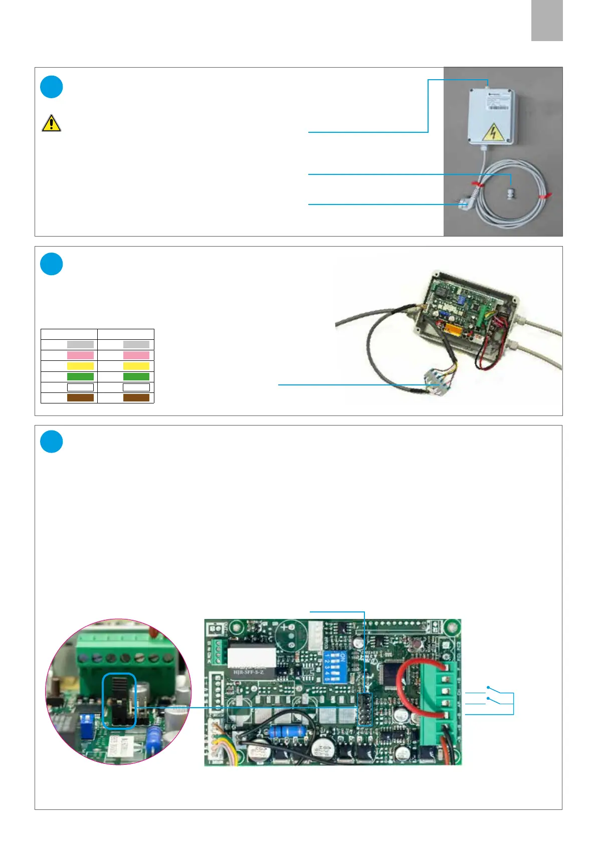
WIRING DIAGRAM
Connect the 6 wires of the motor cable to the
terminal board, following the diagram colours:
Note: the outlet position of the cables may dier from the
one shown alongside.
Caution: the electrical preparation operations must
only be performed by skilled personnel.
27
26
Choose the correct type of buttons:
SEQUENTIAL BUTTON (IMPULSIVE, NOT POWERED):
WARNING: DO NOT REMOVE the JUMPER of the CONNECTOR J3
Connection between the terminal (-B) and the terminal (CH) (closing).
With this type of button automatic reclosing can be enabled (see par. 32).
TWO SEPARATE PUSHBUTTONS (IMPULSIVE, NOT POWERED):
CAUTION: REMOVE THE J3 CONNECTOR JUMPER
Connect the common wire of the button to terminal (-B), the opening contact to terminal (AP) and the closing
contact to terminal(CH).
Drill the junction box using a suitable bit, fit the PG cable gland supplied with the kit, and route the button cable
through it.
CONNECTING THE OPENING BUTTONS
28
Jumper on connector J3
Common
Open
Close
Button inputs:
(dry contacts not
powered)
J3 connector
MOTOR CABLE INLET
230V POWER CABLE
TERMINAL BOARD
BOARD SIDE MOTOR SIDE
Grey Grey
Pink Pink
Yellow Yellow
Green Green
White White
Brown Brown
 Loading...