EasyManua.ls Logo

SDC Exit Check 101-DE - User Manual

SDC Exit Check 101-DE
12 pages
Print Icon
To Next Page IconTo Next Page
Loading...
INSTALLATION INSTRUCTIONS
101-DE/101-KDE
Features:
Egress Delay
15 or 30 second exit delay
1 or 2 second nuisance delay
Built-In 3 Function keypad
Alarm and lock reset
1 to 30 second bypass
Sustained bypass
Additional keyswitch optional
Control Inputs
1 to 30 second request-to-exit and bypass
input with anti-tailgate and jumper
selectable door prop alarm.
Reset
Built-In Annunciation
Armed mode
Nuisance mode
Irreversible egress mode
Release mode
Digital countdown mode
Field selectable voice notification or tone
Field selectable male voice with security
message or female voice with safety
message
Monitoring Outputs
Armed mode
Egress initiation status
Released status
Optional EMLock Outputs
Door position sensor indicates door
open and door closed, commonly used to
verify egress after release.
Magnetic bond sensor – indicates locked
with full holding force, low holding force,
unlocked and tampering.
Triggering Options
Egress alarm triggered by door
movement when used with SDC
1500DE series EMLocks.
Trigger input from external device
field selectable (N/O or N/C)
Field selectable automatic or manual
power up after emergency release or
power loss. Use of manual power up
complies with California Building Code
(OSHPD) requirements.
Code Compliance
IFC International fire Code
IBC International Building Code
NFPA 101 Life Safety Code
NFPA 1 Uniform Fire Code
California Building Code
P:\INSTALLATION INST\Delayed Egress\INST-101DE_KDE.vsd Rev F 05-16 Page 1
Any suggestions or comments to this instruction or
product are welcome. Please contact us through
our website or email engineer@sdcsecurity.com
Application:
When unauthorized egress is initiated SDC Exit Check
®
delays egress
through the door for 15 seconds (or 30 seconds). Meanwhile, the person
exiting must wait while personnel or security responds. The door unlocks
after 15 seconds have elapsed permitting egress. When powered by a fire
control supervised power supply, the lock will release immediately in an
emergency. The integral digital keypad eliminates the need to carry and
locate keys for reset and bypass functions.
Choice of Mounting
Recessed mounted
(3 gang metal plaster ring included)
Surface mounted with optional 3 gang
box (DEC-J)
Optional shroud (SHD-J) to be used with
DEC-J surface box.
Exit Check
®
applications include:
Restricting the egress of wandering patients for their own safety.
HUGS
®
Infant Protection System compatibility
Restricting the egress of commercial center patrons for security application needs.
Controlling pedestrian traffic in transportation facilities, including airport jetways and tarmacs
Reducing Shoplifting and Employee Theft
Display Modes
Door armed and locked.
Alarm countdown has ended,
door is unlocked and alarm sounding
until reset.
Door unlocked and alarm is shunted
(REX or Bypass)
Door has been opened after REX,
Bypass or Alarm.
15
00
--
--
--
--
801 Avenida Acaso, Camarillo, Ca. 93012 • (805) 494-0622
www.sdcsecurity.com • E-mail: service@sdcsecurity.com
Verbal Exit Instructions or
Alarm Tone Only and
Digital Countdown Display
Question and Answer IconNeed help?

Do you have a question about the SDC Exit Check 101-DE and is the answer not in the manual?

SDC Exit Check 101-DE Specifications

General IconGeneral
Operating Temperature32 to 122° F (0 to 50° C)
Dimensions4.5" x 4.25" x 1.25"
Device TypeController
Model101-DE
Input Voltage24V DC

Summary

Installation Instructions Overview

Application

Details the intended uses and scenarios for the SDC Exit Check® system.

Features

Lists the various capabilities and functionalities of the 101-DE/101-KDE controller.

Code Compliance

Outlines the building and fire codes the SDC Exit Check® system adheres to.

101-DE;101-KDE Operational Description

Activation and Alarmed Release

Explains how the Exit Check system is activated and triggers an alarm or release.

Reset and Relock Procedures

Details the procedures for resetting the system and relocking the door.

Request to Exit and Authorized Bypass

Covers how to initiate an authorized exit or bypass the system for free egress.

NFPA-101 and Code Compliance

Specifies how the 101-DE/101-KDE complies with NFPA-101 and other related codes.

BOCA;Chicago Code Compliance

Details compliance with BOCA National Building Code and Chicago Building Code.

System Wiring Diagrams

Single Door with Latching Hardware Wiring

Illustrates the wiring configuration for a single door with latching hardware.

Wiring for Specific Magnetic Lock Models

Wiring details specific to the 1511DE, 1571DE, and 1581DE magnetic lock models.

Installation and Mounting Methods

Key Cylinder Installation

Instructions for installing a key cylinder on the KDE model.

Recessed Dry Wall Mounting

Steps for recessing the unit into a dry wall.

Surface Mount Over Existing Box

Procedure for surface mounting using a 3-gang box over an existing 2-gang box.

Surface and Outdoor Mounting Options

Surface Mount 3 Gang Box to Wall

Guide for surface mounting the 3-gang box to a wall.

Outdoor Wall;Post Mounting with Shroud

Instructions for mounting outdoors on walls or posts with a weather shroud.

Recommended Mounting Procedure Details

Temporary Unit Hanging for Wiring

Using screws to temporarily hang the unit for wiring purposes.

Preventing Faceplate Damage

Sliding packing foam between the wall and unit to prevent damage.

Product Models and Specifications

Delayed Egress Controller Models

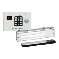
Details the 101-DE and 101-KDE delayed egress controllers.

Magnetic Lock Models

Lists magnetic locks with integrated activation sensors (1511DE, 1571DE, 1581DE).

Lock Finish Options

Lists available lock finish options for the devices.

Optional Outputs Description

Describes the available optional outputs for the controllers.

Available Accessories

Lists and describes available accessories for the system.

General Controller Specifications

Provides input, output, and mechanical specifications for the controller.

System Operation and Keypad Programming

Power-Up Modes

Describes system behavior upon power-up in unlocked or locked states.

Delayed Egress and Alarmed Modes

Explains operation during delayed egress and when the door is unlocked with alarm.

Reset, Authorized Egress, and Bypass

Covers reset procedures and authorized exit/bypass functions via keypad.

Keypad Programming Overview

Introduces keypad programming, status LEDs, and factory codes.

Keypad Programming and Settings

Changing the Master Code

Procedure for changing the default master code for enhanced security.

Entering and Exiting Programming Mode

Steps to enter and exit the system's programming mode.

User Management (Add;Delete Users)

Instructions for adding new users or deleting existing users and their codes.

Erasing All Users and Resetting Defaults

Procedure to erase all users and reset the master code to default.

Returning to Factory Default Settings

Method to restore the keypad and controller to factory default settings.

System Connectivity and Accessories

Connecting to Infant;Patient Monitoring System

Guide for integrating the Exit Check with a patient monitoring system.

Connecting Optional Accessories

Instructions for connecting optional accessories like remote speakers and bypass switches.