Do you have a question about the Sea Tel 3011W-91 and is the answer not in the manual?
Compliance statement for radio equipment and telecommunication terminal equipment.
Statements regarding FCC regulations for satellite communication systems.
Details on AC power and coaxial cables used in the system.
Information on external inputs like Gyro Compass, GPS, and phone.
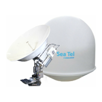
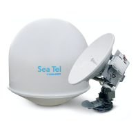
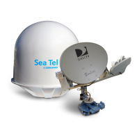
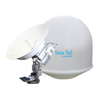
Visual representation of the system's main groups and components.
Setup for using two antenna systems for uninterrupted service.
Panel for managing signal distribution between two antennas.
Protocol for information exchange between antenna controller and modem.
Criteria for choosing an antenna mounting location on a vessel.
Avoiding obstructions that degrade satellite signal quality.
Considerations for creating a stable and suitable mounting platform.
Impact of mounting height on antenna performance and stability.
Different types of masts and their suitability for antenna mounting.
Ensuring safe access for maintenance and servicing of the Above Decks Equipment.
Recommended placement for ACU, TMS, and modems.
Routing, installation, and protection guidelines for system cables.
Proper grounding procedures for safety and system integrity.
Procedures for safely unpacking and checking system components.
Important notes and safety warnings for system assembly.
Instructions for mounting the Above Decks Equipment (antenna assembly).
Specific steps for installing the radome assembly.
Essential step to remove restraints before energizing the antenna.
Detailed guidance on routing and securing shipboard cables.
Procedures for installing ACU, TMS, and other below-deck components.
Connecting various BDE components as per the system block diagram.
Specific connection details for the Antenna Control Unit.
Wiring and connection instructions for the TMS.
Verifying all connections and installations before powering up.
Steps for safely powering on the ACU and antenna system.
Procedures for balancing the antenna and monitoring motor drive torque.
Detailed steps for balancing the antenna and interpreting motor torque data.
Setting ship information, satellite data, and initial parameters.
Navigating and accessing system setup menus.
Factory default settings for key ACU parameters.
Procedure to save configuration changes into ACU's NVRAM.
Selecting the correct gyro compass interface signal type.
Step-by-step process to manually update the gyro type parameter.
Configuration for systems without a gyro compass input.
Calculating and entering the Intermediate Frequency for tracking.
Entering the Kilohertz rate for tracking frequency.
Setting the Forward Error Correction rate for the L-Band SCPC receiver.
Configuration of tone control for multiband LNBs in VSAT systems.
Volt control for multiband LNBs in VSAT systems.
Optimizing antenna feed polarization for the satellite signal.
Setting Network Identification for external network lock.
Settings for single-band LNBs for cross-polarization.
Settings for dual-band LNBs for cross-polarization.
Settings for tri-band LNBs for cross-polarization.
Default settings for quad-band LNBs for cross-polarization.
Settings for single-band LNBs supporting both cross and co-polarization.
Settings for dual-band LNBs supporting both polarizations.
Settings for tri-band LNBs supporting both polarizations.
Settings for quad-band LNBs supporting both polarizations.
Automatic calculation and setting of azimuth and elevation trim parameters.
Step-by-step process to manually adjust antenna pointing for optimal signal.
Adjusting elevation trim offset to correct alignment errors.
Adjusting azimuth trim offset for installation alignment.
Method for electronically calibrating the home flag offset.
Procedure to adjust HFO when home pointing is left of the bow line.
Procedure to adjust HFO when home pointing is right of the bow line.
Steps to input the calculated Home Flag Offset value into the ACU.
Physical adjustment of the home flag sensor and tab.
Overview of the automated search process after signal loss.
Settings for searching satellites in inclined geosynchronous orbits.
Search pattern configuration when a gyro compass is not available.
Adjusting parameters like AUTO THRES, STEP SIZE, and DELAY for search.
Saving modified search parameters to NVRAM.
Programming azimuth limits to create blockage or hazard zones.
Saving configured blockage and hazard zone parameters.
Configuring jumpers on the Terminal Mounting Strip for modem functions.
Specific setup for iDirect modems, including jumpers and parameters.
Specific setup for Comtech modems, including jumpers and parameters.
Specific setup for Hughes modems, including jumpers and parameters.
Specific setup for STM modems, including jumpers and parameters.
Wiring instructions for connecting the ACU to various satellite modems.
Configuring system functions via the SYSTEM TYPE parameter.
Testing the blockage output function and its interface with modems.
Verifying the satellite modem lock input signal to the ACU.
Saving modem connection and setup parameters.
Entering satellite skew value to optimize polarity angle.
Setting POL TYPE, OFFSET, and SCALE for polarity adjustment.
Procedure to peak receive signal by adjusting SAT SKEW.
Minimizing transmission effects on opposite polarization for isolation.
Navigating and accessing system setup menus.
Setting CCW polarity servo position reference.
Setting 5V polarity servo motion scale factor.
Issuing diagnostic commands to the PCU.
Monitoring results of diagnostic commands.
Disabling/enabling DishScan for specific tests or diagnostics.
Adjusting satellite reference mode for gyro stabilization.
Saving modified remote parameters to NVRAM.
Initial checks of the ACU and antenna system after power-up.
Verifying the GPS antenna updates positional information correctly.
Testing if the ACU heading display follows the ship's gyro compass.
Simulating blockage to test SW2 output logic and modem mute functions.
Testing the antenna's tracking accuracy in all four quadrants.
Verifying internet connectivity and data transfer speeds.
Testing the functionality of Voice Over IP communication services.
Details on the system's warranty coverage and limitations.
Common ACU issues and initial troubleshooting steps.
Diagnosing and resolving issues related to gyro compass input.
Steps to install physical restraints to secure the antenna during transit.
Crucial step to remove restraints before energizing the antenna.
Procedure for removing the elevation axis shipping restraint.
Procedure for removing the cross-level axis shipping restraint.
General, front panel, rear panel, and interface specifications.
Specifications for Synchro, SBS, Control, and NMEA interfaces.
Operating temperature, humidity, and other environmental requirements.
Power requirements for the DAC-2202 unit.
Specifications for the antenna's reflector, feed, polarization, and gain.
Technical details of the SMW Quad Band LNB.
Specifications for the transmit radio package, including BUC.
Power supply specifications for the Block Up-Converter (BUC).
Specifications for Co-Polarization components like diplexers and LNBs.
Technical specifications for the PCU, including connectors and controls.
Specifications for the MDE, including motor drivers and connectors.
Specifications for the 400 MHz modems used in the system.
Details on the pedestal's stabilization, motors, and motion range.
Specifications for the 40-inch radome, including dimensions and material.
Power input requirements for the Above Decks Equipment pedestal.
Environmental operating conditions like temperature, humidity, and wind.
Reference to specifications for ACU, TMS, and Satellite Modem.
Reference to manufacturer's manual for router specifications.
Recommendations for L-Band IF coax and multi-conductor cables.
Drawings related to the DAC-2202 ACU assembly and schematics.
Drawings specific to the 3011W-91 Ku-Band model.
General drawings for the 3011 system, including schematics and block diagrams.