Do you have a question about the Sea Tel 5012-33 and is the answer not in the manual?
| Polarization | Linear |
|---|---|
| Stabilization | 3-axis |
| Tracking | Automatic |
| Antenna Diameter | 1.2 m |
| Frequency Band | C-band |
Details on AC Power & Coaxial cables for the system.
Describes multi-conductor cables from ship systems like Gyro, GPS, etc.
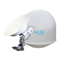
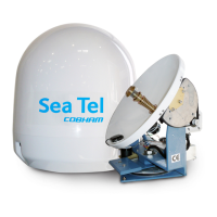
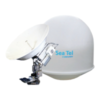
Overview of the system's two main groups: Above Decks (ADE) and Below Decks (BDE).
Explains setting up dual antennas for uninterrupted service due to blockage.
Details the ASCII message protocol for antenna-modem communication.
Guidelines for choosing the optimal mounting location for the radome assembly on a ship.
Discusses how structures can degrade the satellite signal and recommends clear line-of-sight.
Covers deck/deckhouse mounting, pedestal sizing, and alignment for the ADE.
Explains how mounting height affects tangential acceleration and antenna performance.
Discusses various mast types (Vertical, Raked, Girder, Truss) for mounting the antenna.
Provides safety guidelines for accessing the Above Decks Equipment.
Recommendations for installing below-decks equipment like ACU in standard racks.
Details on selecting and installing coaxial, power, and signal cables for the system.
Procedures for grounding the ADE and pedestal to the ship's hull for safety.
Steps for unpacking the equipment and inspecting for shipping damage.
Important notes on using Loctite and torque values for fasteners during assembly.
Procedures for preparing and installing the Above Decks Equipment (ADE) radome assembly.
Instructions for grounding the antenna pedestal to the ship's hull using straps or wire.
Steps to remove shipping restraints from AZ, EL, and CL axes before energizing the antenna.
General cautions and warnings for installing below-decks equipment.
Connecting AC power and various interface cables for below-decks equipment.
Performing visual, electrical, and wiring checks before energizing the system.
Initial setup, calibration, and commissioning of the MXP for antenna operation.
Selecting the correct gyro interface type for accurate heading input and stabilization.
Procedures for operating without a gyro compass using "No Gyro" or "Fixed" modes.
Calculating and entering the IF tracking frequency for satellite acquisition.
Optimizing feed polarization by entering satellite skew values for accurate targeting.
Adjusting the Home Flag based on large AZ TRIM values or observed bow pointing errors.
Setting the Home Flag parameter when the offset is greater than +/-5 degrees.
Using AZ TRIM for small offsets (+/-5 degrees) to correct antenna pointing.
Automatic calculation and setting of Azimuth and Elevation trim offsets for accurate targeting.
Step-by-step procedure for manually calibrating antenna targeting using calculated and peak positions.
Steps when the system automatically acquires the satellite and achieves network lock.
Troubleshooting steps when the system fails to automatically find a satellite.
Actions when the system finds a satellite signal but fails to achieve modem network lock.
Procedure for selecting and targeting a different satellite from the Satellite Search screen.
Procedure for contacting the NOC to arrange and perform cross-pol isolation testing.
Specifications for the antenna reflector, feed assembly, LNBs, and gain.
Specifications for the SSPB (Block Up-Converter) and associated RF components.
Details on the AC input, DC output, and power consumption of the BUC power supply.
Technical specifications for the SMW Quad Band Low Noise Block downconverter.
Connectors and features of the Integrated Control Unit (ICU).
Connectors and status LEDs for the Motor Driver Enclosure (MDE).
Specifications for the pedestal's type, stabilization, motors, and motion range.
Environmental and input voltage specifications for the integrated GPS module.
Dimensions, weight, RF attenuation, and maintenance for the 66-inch radome.
Operating conditions including temperature, humidity, wind, spray, icing, rain, and corrosion.
Compliance with ISTA standard for drop (transit shock) conditions.
Physical dimensions, voltage, weight, and interface types for the MXP.
Details on MXP control interface, band select, blockage mute, and NMEA interface.
Environmental conditions for the Below Decks Equipment (BDE).
Specifies the total system weight for the Above Decks Equipment (Pedestal & Radome).
Power consumption details for the ADE and BDE units.
Lists compliance standards for shock, vibration, EMI/EMC, safety, and FCC.
Recommended 50-ohm coax cable types and specifications for L-Band IF connections.
Index of specific drawings related to the 5012-33 Ku-Band system.