EasyManua.ls Logo

SEA Orion User Manual

Default Icon
4 pages
To Next Page IconTo Next Page
Page #1 background imageLoading...
Page #1 background image
SEA S.r.l. Zona Ind.le S. Atto Teramo Italia
Sito Internet: http://www.seateam.com
E-mail: seacom@rgn.it (Uff. Commerciale) seatec@rgn.it (Uff. Tecnico)
Cod. 67410170 Rev. 02 , 06/2001 Pag. 1 di 4
MPU/EO ORION WITH REVERSE LOGIC
(cod. 23005005)
Circuit board layout
Fig. 1
LD1: Start Led
CN3: Main Terminals
LD2: Stop Led
CN4: Radio Receiver Terminals
LD3: Photocell Led
CN5: Limit Terminals
LD4: Pedestrian Start Led
CN6: Power Supply Connector 220/240V
LD5: Close Limit Led (with DIP3 = ON)
CN7: Motor Condenser Terminals
Open Limit Led (with DIP3 = OFF)
FST1: Earth Tag
LD6: Open Limit Led (with DIP3 = ON)
RL1: Brake Relay
Close Limit Led (with DIP3 = OFF)
RL2: Motor Relay
LD7: Indicator Led
RL3: Direction Relay
F1: Accessory Fuse 2 A
DIP1: Excludes Reverse
F2: Motor Fuse 5 A (T)
DIP2: Selects Functioning Logic
T1: Transformer
DIP3: Selects Gate Direction
CN1: Rev. Sensor Terminals
TR1: Time regulation Trimmer
CN2: Motor Terminals
TR2: Brake regulation Trimmer
T1
RL1
FST1
DIP1
TR1
DIP3
DIP2
CN5
CN1
1
2
3
4
5
LD4
F2
RL2
RL3
F1
CN7
CN2
CN6
Question and Answer IconNeed help?

Do you have a question about the SEA Orion and is the answer not in the manual?

SEA Orion Specifications

General IconGeneral
BrandSEA
ModelOrion
CategoryControl Unit
LanguageEnglish

Summary

MPU/EO Orion Control Unit Overview

Circuit Board Layout

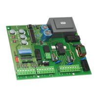
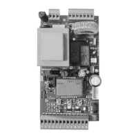
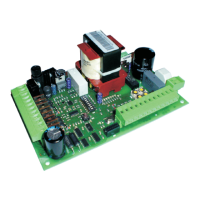
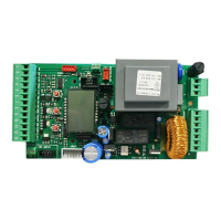
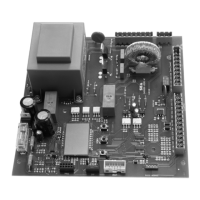
Visual representation of the MPU/EO Orion circuit board components and their arrangement.

Electrical Connections and Wiring

Main Terminal Connection Blocks (CN3/CN6)

Details the wiring and connections for the main terminal blocks CN3 and CN6.

Mains Earth Connection (FST1)

Instructions for connecting the FST1 earth point for safety and system grounding.

MPU/EO Functionality and Operation

Electronic Brake Adjustment

Explains how to adjust the electronic braking action using Trimmer TR2 for stopping intensity.

Electronic Reverse Device

Describes the electronic reverse function, clutch adjustment, and obstacle detection during operation.

Logic Selection (DIP2)

Details how to select operational logic (Semi-automatic/Automatic) using DIP2.

Gate Stopping Position Setup

Brake Regulation Procedure

Gate Closing Direction Selection

Diagnostic Function

Programming Tables

Trimmer Adjustments and Radio Connection

Time Regulation Trimmer (TR1)

Details the function of Trimmer TR1 for time regulation settings.

Brake Adjustment Trimmer (TR2)

Details the function of Trimmer TR2 for brake adjustment settings.

Radio Connection (CN4)

Lists the connections for the radio receiver, including START and PED. START inputs.

Safety Precautions and System Requirements

General Safety Precautions

General electrical installation safety guidelines and cable management recommendations.

Conformity Requirements

Lists the directives and standards the MPU/EO unit conforms to, including EMC and safety.

Product Information and Support

Intended Use

Specifies the intended application of the MPU/EO control unit for sliding gates.

Limit of Guarantee

Details the guarantee period and conditions for the MPU/EO unit.

Related product manuals