DOCS-010 Manual, SeaBotix Inc. Users, 200 Series – 18 Mar 09 - Rev B - Page 11 of 52
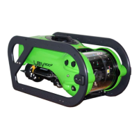
1.3.2 Integrated Control Console
1) Ensure that the Circuit Breaker (A.) is off,
(down position.)
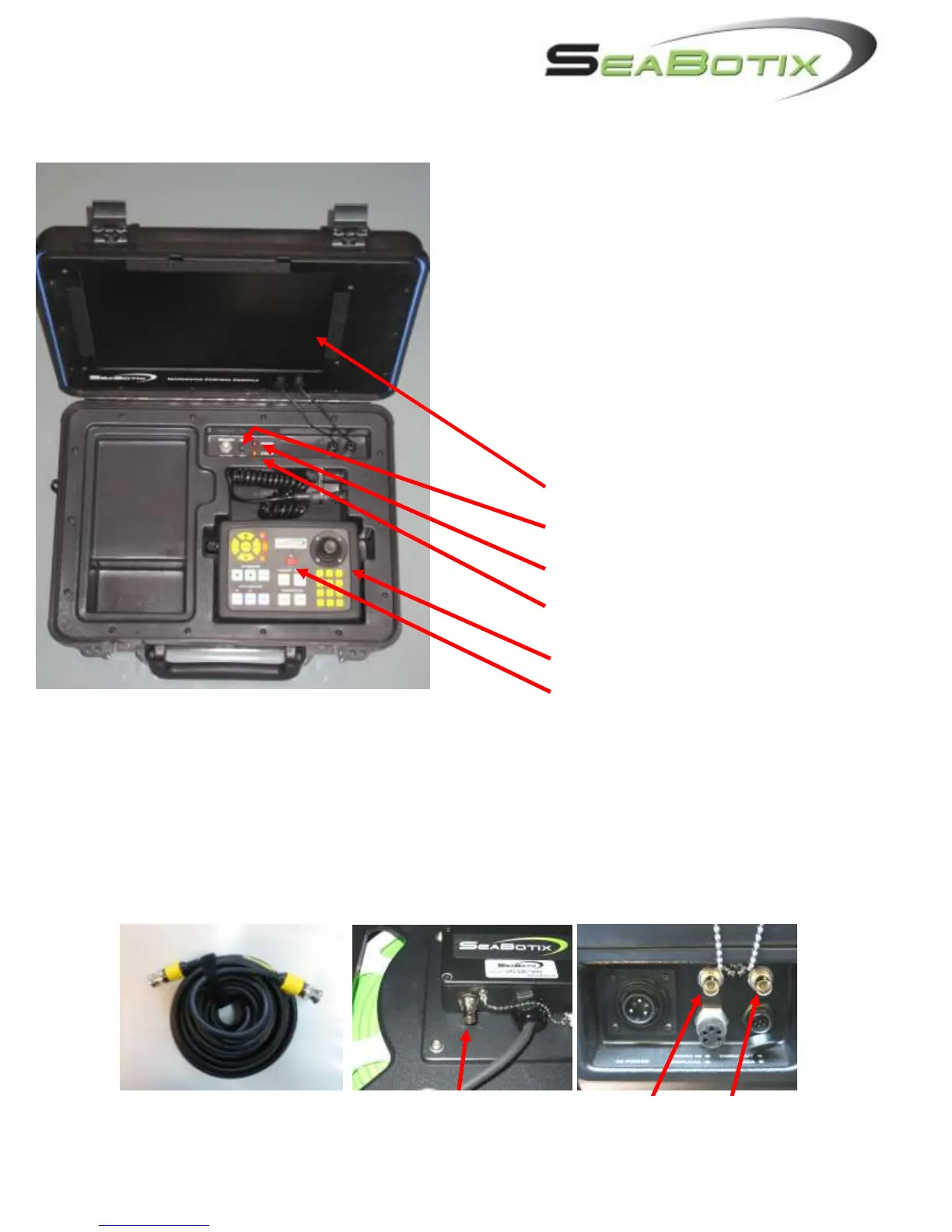
2) Engage the tether connector. On the
Surface Power Supply, ensure that the
red dots line up.
3) Plug the power cord into the ICC,
securing the locking collar. Now plug the
other end into the power outlet.
4) Note that there is a 6-contact RS-232
connector. This will be used for “flashing”
the LBV or when operating Tritech sonar
and/or Linkquest tracking.
A. Monitor
B. Circuit Breaker
C. Red LED – POWER
D. Amber LED – STATUS
E. Operator Control Unit (OCU)
F. OCU Power Switch
1.3.3 LBV150SE and LBV200L (Fiber Optic Video) Systems:
These LBVs come with tether reels that are designed for fiber optic video. Video is output at
the reel hub. Therefore, the hub and the ICC must be connected by a coaxial video cable.
CBA066 (a 7M, BNC-BNC coaxial cable) should be connected to the „Video-Out‟ BNC jack
on the reel hub and the „Video In‟ BNC jack on the ICC. The Video Out is used for
additional display or recording devices.