Section02MAINTENANCE
Subsection 03 (WATER-FLOODED ENGINE)
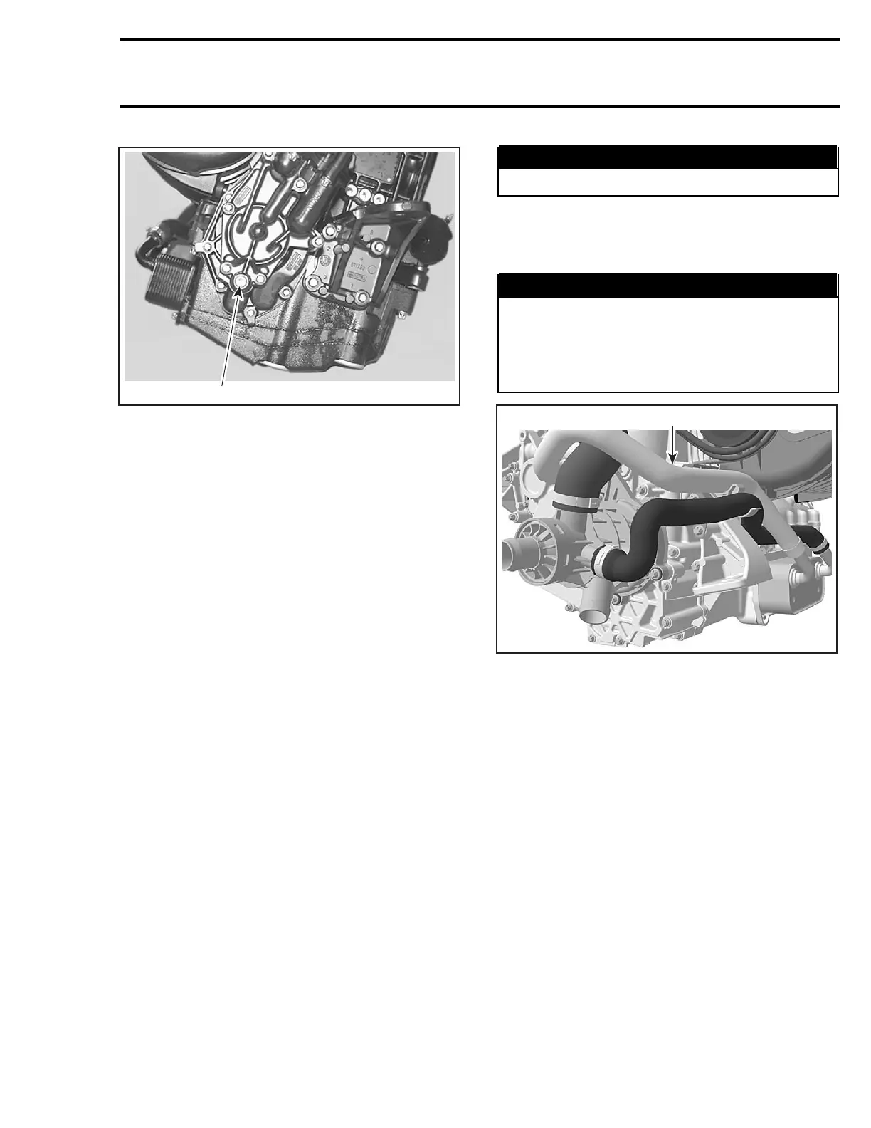
1
F18D19A
1. Scavenge oil pump cover drain plug
– Connect the oil vac tool Bombardier (P/N 529
035 880) to the fitting.
– Thefrontoftheenginemustbetilteddownap-
proximately 15 degrees to facilitate the removal
of the oil. Raise the rear of the boat according-
ly. Siphon the oil from the fitting.
– Level the engine.
– Remove the oil vac tool and the fitting. Apply
Loctite 243 and reinstall the drain plug.
NOTE: If spillage occurs, clean immediately with
the Pulley flange cleaner (P/N 413 711 809) to pre-
vent oil stains.
– Install a new oil filter and reinstall the oil filter
cap.
– Fill up the reservoir with fresh oil.
– Boil out the remaining water as follows:
• Recommended procedure: BOIL OUT PRO-
CEDURE IN A TEST TANK OR TIED TO A
TRAILER WITH WATERCRAFT IN WATER.
• Optional procedure: BOIL OUT PROCE-
DURE CONNECTED TO A FLUSH KIT.
Refer to instructions below.
Boil Out Procedure
NOTE: This procedure is intended to evaporate
the water contained in the oil.
Procedure in a Test Tank or Tied to a Trailer
with Watercraft in Water
– Run the engine for 5 minutes at 3500 RPM.
WARNING
Make sure to safely secure the watercraft.
– With the engine still running at 3500 RPM, in-
stall a hose pincher to the coolant line going to
the oil cooler.
WARNING
Certain components in the engine compart-
ment may be very hot. Direct contact may re-
sult in skin burn. Do not touch any electrical
parts or jet pump area when engine is run-
ning.
1
F18E1QA
1. Oil cooler coolant inlet hose
– Continue to run the engine at 3500 RPM for 15
more minutes (20 minutes total run time).
– Shuttheengineoff.
– Remove the hose pincher on the coolant line
going to the oil cooler.
CAUTION: Hose pincher must be removed pri-
or to operating the watercraft. Failure to do
this will result in damage to the engine.
– Change the oil and filter again.
– Procedure is now completed.
Procedure Connected to a Flush Kit
– On drive shaft, remove the C-clip then move
forward the ring seal carrier. Refer to D
RIVE
SYSTEM section.
CAUTION: Make sure that the ring seal carrier
is not in contact with the PTO seal assembly,
neither with the carbon ring.
– Connect a flush ki
t to the coolant line.
smr2004-Complete Line Up 37
 Loading...


