vertical resonant frequency of
25
Hz
or
lower. A minimum clearance
of
0.050 inches should be allowed around the entire perimeter of the
drive
to allow for cooling airflow and motion during mechanical shock
or
vibration. I
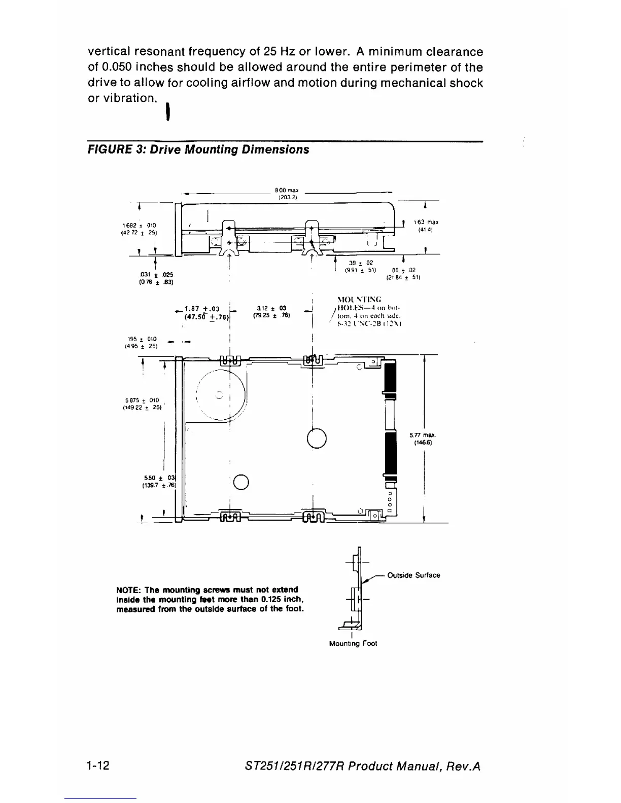
FIGURE 3:
Drive
Mounting Dimensions
1'95!
010
(495
± 25)
5e75
+ 010
('49
22-
±
25~
I
_
1.87
+
.03
f-
(47.50
±.76tl
3.12
.t
03
(79.25
,16)
NOTE:
The mounting screws must not extend
Inside
the mounting feet more than
0.125
inch,
measured from the outside surface
of
the foot.
I
~
I
;
I
I
b
Mounting Foot
S.77
mall.
1'466)
Oulside Surlace
1-12
ST2511251
RI277R
Product
Manual, Rev.A