2.0 DRIVE CONFIGURATION
The ST2S1/2S1R/277R
may
be configured
for
specific system require-
ments.
2.1
DRIVE CONFIGURATION SHUNT
J7
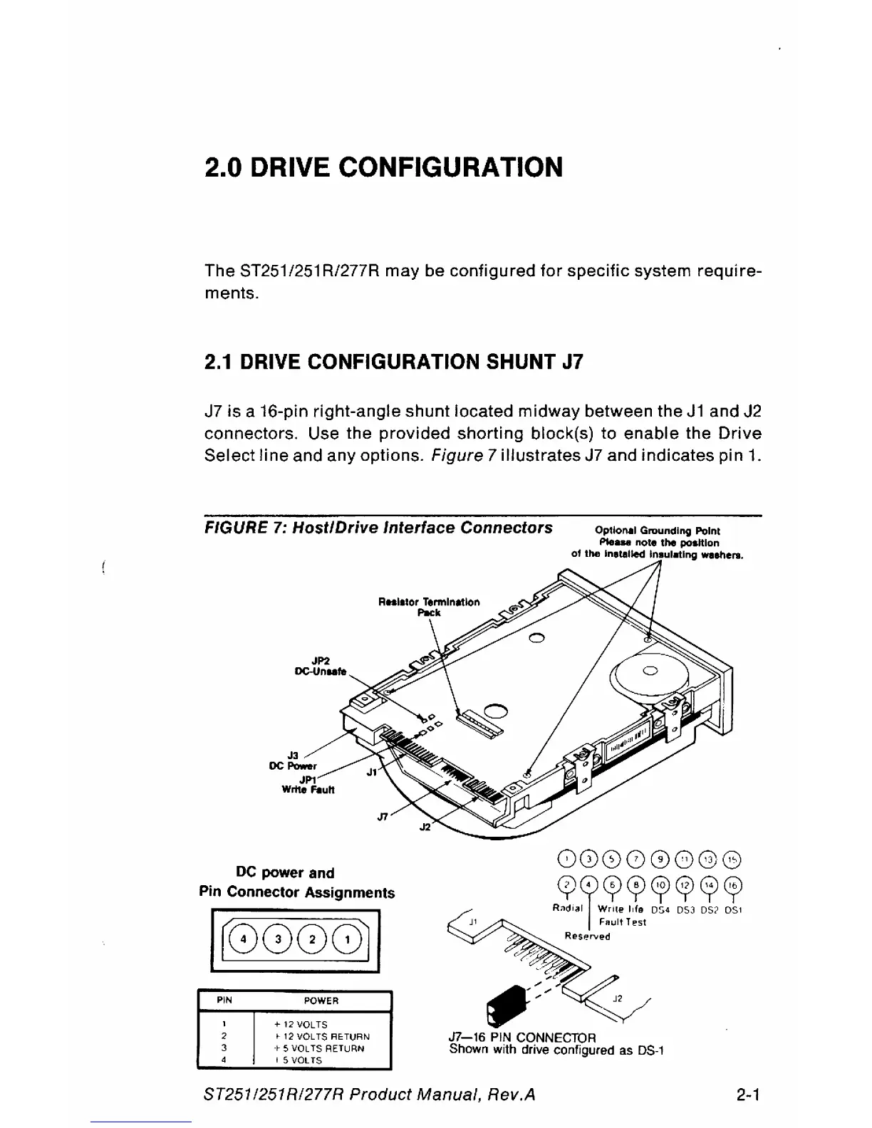
J7 is a 16-pin right-angle shunt located midway between the
J1
and J2
connectors. Use the provided shorting block(s) to enable the
Drive
Select
line
and any options.
Figure
7 illustrates J7 and indicates pin
1.
FIGURE 7:
Host/Drive
Interface
Connectors Optional Groundl"1l Point
PIe_
note
the
position
of
the
Inltalled Inaulatl"1l Willie
...
JP2
DC-Un
..
te
J3
DC_r
JPl
Write
FIoutl
DC
power and
J7
Pin Connector Assignments
Ir
8888
JI
PIN
POWER
I
+
12
VOLTS
~.
12
VOL
TS
RETURN
+ 5 VOLTS RETURN
15
VOLTS
R:P.~W~P.~~~~
r I FRuit
T~'.i1
Re5~n",!!'d
J7-16
PIN CONNECTOR
Shown with drive configured as
DS·1
8T251
1251
RI277R Product Manual, Rev.A
2-1