Do you have a question about the Seagull Models Extra 300S and is the answer not in the manual?
Fit the dihedral brace to wing halves, sand if needed, and apply epoxy for joining.
Insert the dihedral brace, join wing halves, and clean excess epoxy.
Install servos into trays, test fit, and route their leads through the wing.
Mark linkage lines, locate control horns, backplates, and screws.
Install the aileron servo tray into the servo mount.
Position aileron horns, drill mounting holes, and secure with screws.
Thread clevis onto each aileron torque rod until flush with ends.
Cut nylon tubes for pickup and vent, bend vent tube, and connect pickup.
Fit stopper assembly, ensure proper tube placement, and tighten screw.
Connect fuel lines, mark tubes, and slide tank into fuselage.
Attach Z-Bend in pushrod wire to carburetor throttle arm.
Trial fit engine, mark pilot holes, and mount engine with bolts and nuts.
Assemble and mount the wheel pants as shown in the pictures.
Assemble wheels, collars, and landing gear, securing with glue.
Align landing gear holes with fuselage blind nuts and mount with bolts.
Align cowl back edge with marks, front edge with crankshaft, and secure.
Install muffler, cut cowl for clearance, and connect lines.
Install spinner backplate, propeller, and cone, securing with screws.
Mark stabilizer centerline, fit into fuselage slot, and align.
Remove covering on stabilizer and fuselage platform for mounting.
Install the horizontal strut support system.
Remove covering from the precut hinge slot in the fuselage.
Slide vertical stabilizer into slot, align, and epoxy in place.
Position elevator horn over hinge line and mount with screws.
Position rudder horn parallel to horizontal stabilizer and mount.
Drill mounting holes through elevator/rudder halves and mount horns.
Install switch into the precut hole in the servo tray and secure.
Attach push-pull lever wire to switch and route it out of fuselage.
Install servos into tray, connect servo arms, and adjust for neutral.
Connect pushrods, turn on radio, and check/reverse servo direction.
Plug servo leads, switch lead, and battery pack lead into receiver.
Wrap and position receiver and battery pack in fuel tank compartment.
Drill hole for antenna, route it out, and secure to vertical stabilizer.
Bolt wing to fuselage, trim and position belly pan under wing.
Remove covering where belly pan contacts wing and glue in place.
Ensure correct center of gravity by adjusting weight for level flight.
Measure and set control throws for initial test/sport and aerobatic flying.
Check elevator, rudder, ailerons, and throttle operation and direction.
Charge batteries, check all bolts and glue joints for security.
Verify control surface movement, dual rates, and airplane balance.
Ensure receiver antenna is extended and propeller is properly balanced.
| Brand | Seagull Models |
|---|---|
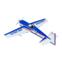
| Model | Extra 300S |
| Category | Toy |
| Language | English |