SPACE WALKER II Instruction Manual
10
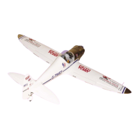
THROTTLE SERVO ARM INSTALLATION.
1) Install adjustable servo connector in
the servo arm .
2) Using a modeling knife, carefully remove
the covering at mounting slot of horizontal sta-
bilizer ( both side of fuselage).
3) Slide the stabilizer into place in the pre-
cut slot in the rear of the fuselage. The stabi-
lizer should be pushed firmly against the front
of the slot.
HORIZONTAL STABILIZER.
1) Using a ruler and a pen, locate the
centerline of the horizontal stabilizer, at the trail-
ing edge, and place a mark. Use a triangle
and extend this mark, from back to front,
across the top of the stabilizer. Also extend
this mark down the back of the trailing edge of
the stabilizer.
Draw center line.
INSTALLING THE SWITCH.
Install the switch into the precut hole in the
side of fuselage.
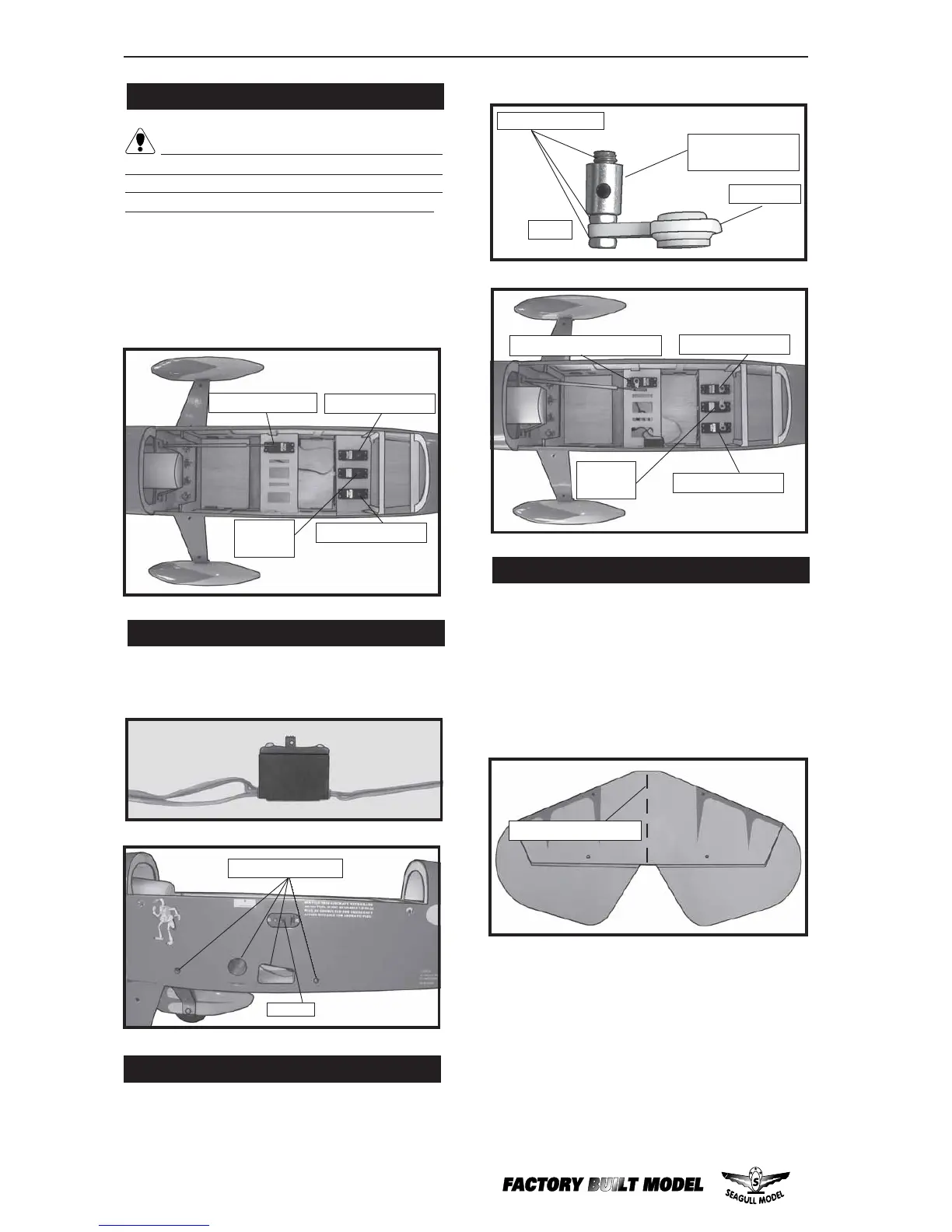
Throttle servo.
Rudder
servo.
Elevator servo.
Elevator servo.
INSTALLING THE FUSELAGE SERVO.
1) Install the rubber grommets and brass
collets onto the throttle servo. Test fit the servo
into the aileron servo mount.
2) Secure the servos with the screws pro-
vided with your radio system.
Because the size of servos differ, you
may need to adjust the size of the precut open-
ing in the mount. The notch in the sides of the
mount allow the servo lead to pass through
.
Switch.
Remove covering.
Adjustable Servo
connector.
Servo arm.
Loctite secure.
Throttle servor arm .
Rudder
servo.
Elevator servo.
Elevator servo.
1 pcs.