INSTALLATION
MANUAL
Section 2: ELECTRICAL INSTALLATION
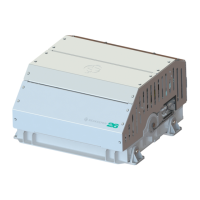
FIGURE 3 – CABLE 2 WIRE CONNECTIONS AT AC POWER DISTRIBUTION PANEL
ii. Connect 230 VAC wires in CABLE 2 to a 20 Amp, double-pole Circuit Breaker at an AC
power distribution panel according to Figure 3 above.
3. DRIVE BOX AC POWER OUTPUT TO SEAWATER PUMP CONNECTION INSTRUCTIONS
a. Cable: 3 x 14AWG (3 x 2.0mm
2
CSA) cable, 10’ (3m) length, Seakeeper supplied pre-
installed.
b. Pumps rated at 230 VAC, 5 Amps max., Customer-supplied.
i. Locate CABLE 5 for AC power output to the Seawater Pump from the Drive Box at the
middle of three cable glands. (See Figure 2.)
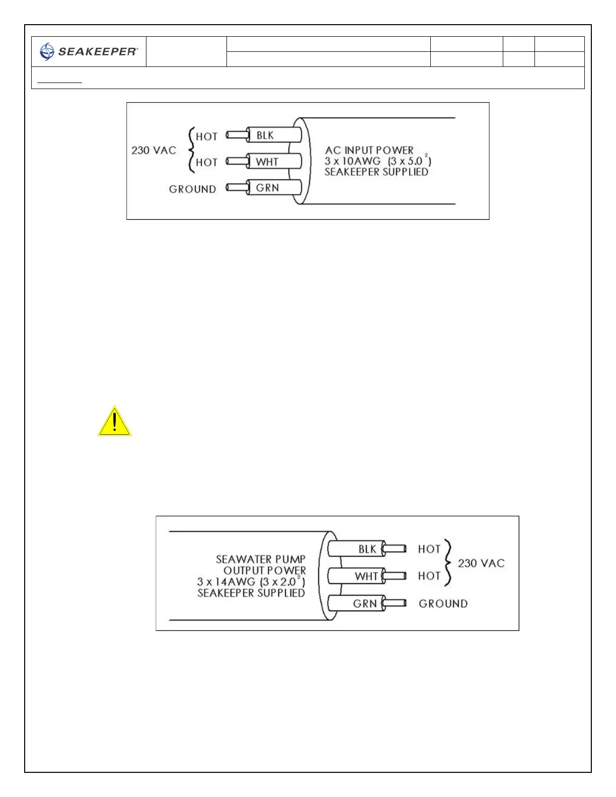
FIGURE 4 – CABLE 5, AC OUTPUT POWER CABLE
ii. Connect the 230 VAC wires in CABLE 5 to a 5 Amp maximum, Seawater Pump
(approximately 1/3 horsepower or 250 W) according to Figures 4 and 5.
Verify that AC power is OFF to the Drive Box before connecting
CABLE 5 to a Seawater Pump.
 Loading...