INSTALLATION
MANUAL
Section 2: ELECTRICAL INSTALLATION
4. 24 VDC POWER SOURCE REQUIREMENTS
a. 24 VDC, 10 Amps.
b. A separate breaker should be used for each Gyro.
5. GYRO DC POWER CONNECTION INSTRUCTIONS
Reversing polarity on the DC power input to the gyro can result in
damaging the electronics in the control system.
a. 24 VDC, 10 Amps. 2 x 12AWG (3 x 4mm
2
CSA) customer supplied.
i. Install Seakeeper provided DC Power Input Cable, P/N: 20248 as CABLE 1.
1. Route CABLE 1 to DC Power Distribution Panel.
2. Terminate RED conductor to +24 VDC. Terminate BLACK conductor to
24V Rtn or Zero VDC.
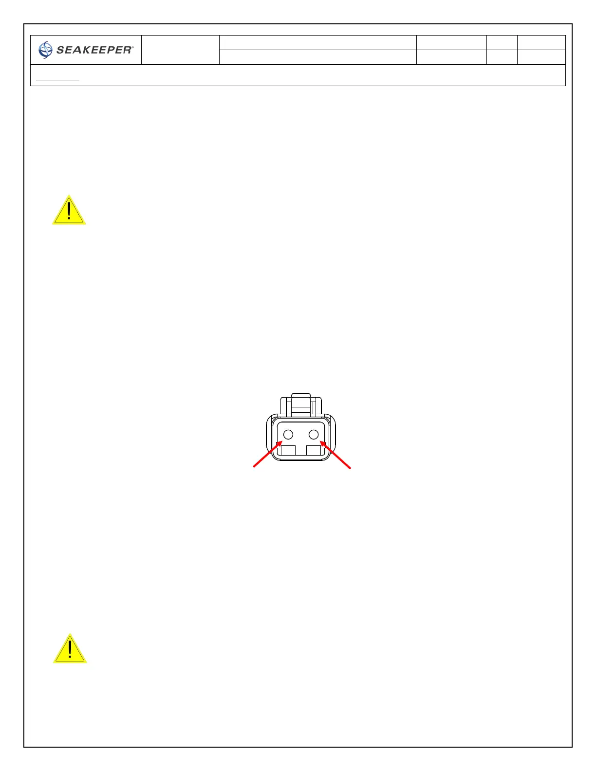
ii. Before connecting CABLE 1 to gyro, check for proper voltage and polarity with a DC
multimeter using Figure 7 below.
iii. Connect CABLE 1 to 24VDC input receptacle on Gyro.
When energizing DC power the first time, if display does not power up
immediately then disconnect and inspect connector polarity.
FIGURE 7 – DC POWER INPUT CONNECTOR
CONTACT ASSIGNMENTS (front)
2
(24V Rtn)
1
(+24VDC)
 Loading...