4.3. CONNECTING THE GAS CYLINDER (SEE SECTION 4.10 REGARDING GAS TYPES)
4.3.1. Place the lower end of the gas cylinder on to the rear tray, between the two wheels. See fig.2-C. Allow the upper part of the cylinder to
rest into the metal support. See fig.2-D. Secure the cylinder by hooking either end of the chain E through the metal support as shown in
fig.2.
4.3.2. When using Argon or Argon mixtures, you will need to use the “bull nose adaptor”. Fit the bull nose adaptor to the cylinder with a
spanner. (If you intend to use CO
²
gas the regulator will t directly onto the cylinder).
4.3.3. Fit the gas regulator on to the bull nose adaptor as shown in g.1.
4.3.4. Push the black gas tube provided (see g.2-A) onto the gas inlet nozzle and retain it with the wire clip provided as shown in fig.2-B.
Push the other end of the tube onto the gas outlet nozzle on the regulator and retain it with the other wire clip provided. See fig.1.
4.3.5. When you are ready to weld set the regulator ow rate to 5-8 litres/min depending on the material to be welded, and whether there are
draughts which are strong enough to disturb the gas ow.
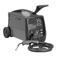
4.4. FITTING A REEL OF WIRE
4.4.1. Open the side compartment on the welder by placing your nger into the black catch and lifting both the catch and the door.
The welder is supplied with a mini spool of mild steel wire, but will accept spools of up to 5kg without modication.
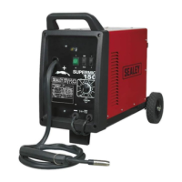
4.4.2. Referring to g.5, rotate the pressure knob (F) anti-clockwise and remove it from the threaded spindle together with the spring
(E) and the top disc (D). Small reels of wire will run on the spindle itself. The larger 5kg wire reel will run on the larger diameter
ange at the base of the reel spindle (A). Place the wire reel (C) onto the spindle ensuring that the wire withdraws from the
spool in a forwards direction and on the same side of the compartment as the wire feed unit. Place the plastic top disc (D)
over the end of the spindle followed by the reel spring (E). Thread the pressure knob (F) onto the end of the spindle and
screw it down clockwise until the spring is partially compressed. The reel take off pressure should be set to provide a mild
braking effect to prevent overrun where loose coils of wire form on the reel. Do not overtighten this knob as too much braking
will conict with the wire tension set on the wire drive unit.
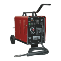
4.4.3. Referring to g.4 turn the knob on the wire lock screw (B) anti-clock wise and unlatch it from the pressure roller moulding. Swing the
pressure roller moulding (A) away from the drive roller.
4.4.4. Straighten 40-50mm of spool wire (do not allow wire to uncoil), and gently push wire through the plastic guide and through the 6 or
8mm feed roller groove and into the torch liner. Refer to section 6.5 on how to reverse the roller for either 6 or 8mm wire.
4.4.5. Refering to g.7, move the pressure roller moulding (A) back round onto the grooved drive wheel and swing the wire lock screw (B) up
to lock it in place. See 4.5.2 regarding wire tension.
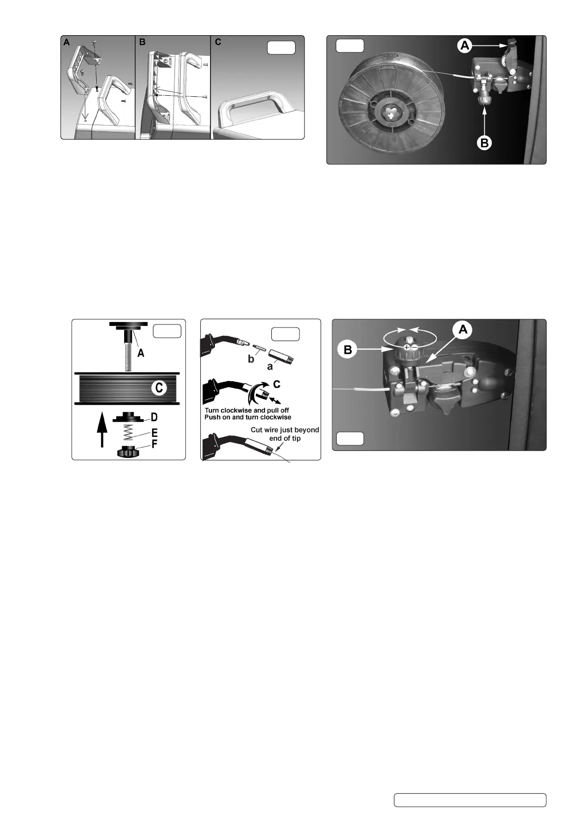
4.5. FEEDING THE WIRE THROUGH TO THE TORCH. (SEE FIG.6)
Remove gas cup (a) and contact tip (b) from end of torch as follows:
a) Take torch in left hand with the torch tip facing to the right.
b) Grasp gas cup rmly in your right hand.
c) Turn gas cup clockwise only and pull cup out to the right.
WARNING! do not turn gas cup anti-clockwise, as this will damage internal spring.
d) Unscrew the copper contact tip (right hand thread) to remove.
4.5.1. Check welder is switched off “0” and that the earth clamp is away from the torch tip. Connect the welder to the mains power supply and
set the voltage switches to MIN/1.
4.5.2. Set the wire speed knob to position 5 or 6. Keeping the torch cable as straight as possible and press the torch switch. The wire will
feed through the torch.
4.5.3. When wire has fed through, switch welder off, unplug from mains.
a) Take torch in left hand and screw contact tip back into place.
b) Grasp gas cup in right hand, push onto torch head and turn clockwise only.
WARNING! do not turn gas cup anti-clockwise, as this will damage internal spring.
c) Cut wire so that it is just protruding from the cup.
Original Language Version
© Jack Sealey Limited
fig.4
fig.3
fig.7
fig.5
fig.6
SUPERMIG150.V4 Issue:1 08/07/22
 Loading...