EasyManua.ls Logo

Sealey SUPERMIG150.V4 - User Manual

Sealey SUPERMIG150.V4
6 pages
Print Icon
To Next Page IconTo Next Page
Loading...
150A PROFESSIONAL MIG WELDER
MODEL NO: SUPERMIG150.V4
Thank you for purchasing a Sealey product. Manufactured to a high standard, this product will, if used according to these instructions,
and properly maintained, give you years of trouble free performance.
IMPORTANT: PLEASE READ THESE INSTRUCTIONS CAREFULLY. NOTE THE SAFE OPERATIONAL REQUIREMENTS, WARNINGS & CAUTIONS. USE
THE PRODUCT CORRECTLY AND WITH CARE FOR THE PURPOSE FOR WHICH IT IS INTENDED. FAILURE TO DO SO MAY CAUSE DAMAGE AND/OR
PERSONAL INJURY AND WILL INVALIDATE THE WARRANTY. KEEP THESE INSTRUCTIONS SAFE FOR FUTURE USE.
1. SAFETY
1.1. ELECTRICAL SAFETY
WARNING! It is the user’s responsibility to check the following:
Check all electrical equipment and appliances to ensure that they are safe before using. Inspect power supply leads, plugs and
all electrical connections for wear and damage. Sealey recommend that an RCD (Residual Current Device) is used with all electrical
products. You may obtain an RCD by contacting your local Sealey stockist.
If the product is used in the course of business duties, it must be maintained in a safe condition and routinely PAT (Portable
Appliance Test) tested.
Electrical safety information, it is important that the following information is read and understood.
Ensure that the insulation on all cables and on the appliance is safe before connecting it to the power supply.
Regularly inspect power supply cables and plugs for wear or damage and check all connections to ensure that they are secure.
Important: Ensure that the voltage rating on the appliance suits the power supply to be used and that the plug is tted with the
correct fuse - see fuse rating in these instructions.
8 DO NOT pull or carry the appliance by the power cable.
8 DO NOT pull the plug from the socket by the cable.
8 DO NOT use worn or damaged cables, plugs or connectors. Ensure that any faulty item is repaired or is
replaced immediately by a qualied electrician.
This product is tted with a BS1363/A 13 Amp 3 pin plug.
If the cable or plug is damaged during use, switch off the electricity supply and remove from use.
Ensure that repairs are carried out by a qualied electrician.
Replace a damaged plug with a BS1363/A 13 Amp 3 pin plug. If in doubt contact a qualied electrician.
a) Connect the GREEN/YELLOW earth wire to the earth terminal ‘E’.
b) Connect the BROWN live wire to the live terminal ‘L’.
c) Connect the BLUE neutral wire to the neutral terminal ‘N’.
Ensure that the cable outer sheath extends inside the cable restraint and that the restraint is tight.
Sealey recommend that repairs are carried out by a qualied electrician.
Cable extension reels. When a cable extension reel is used it should be fully unwound before connection. A cable reel with an RCD fitted
is recommended since any product which is plugged into the cable reel will be protected. The section of the cable on the cable
reel is important and should be at least 1.5mm², but to be absolutely sure that the capacity of the cable is suitable for this product
and for others that may be used in the other output sockets, we recommend the use of 2.5mm² section cable.
WARNING! Be very cautious if using a generator to power the welder. The generator must be self-regulating and stable with
regard to voltage, wave form and frequency. The output must be greater than the power consumption of the welder. If any of
these requirements is not met the electronics within the welder may be affected. NOTE: The use of an unregulated generator
may be dangerous and will invalidate the warranty on the welder.
WARNING! The welder may produce voltage surges in the mains supply which can damage other sensitive equipment e.g. computers. To
prevent this happening, it is recommended that the welder is connected to a power supply that does not feed any sensitive equipment.
IMPORTANT! If using welder to full capacity, we recommend a 16amp supply. We recommend you discuss the installation of a 16amp
industrial round pin plug and socket with your electrician.
SUPERMIG150.V4 Issue:1 08/07/22
Original Language Version
© Jack Sealey Limited
Refer to
instructions
Electric shock
from welding
electrodes can
kill.
Hot surfaces
Breathing
welding
fumes can be
hazardous to
your health.
Electromagnetic
elds can cause
pacemaker
malfunction.
Wear eye
protection
Wear protective
gloves
Welding sparks
can cause
explosions or
re.
Arc rays can
burn eyes and
injure skin.
Wear safety
footwear
Wear protective
clothing
Warning!
Keep away
from rain
Warning!
Electricity
Shock hazard
Recommended fuse rating
13 Amp
Question and Answer IconNeed help?

Do you have a question about the Sealey SUPERMIG150.V4 and is the answer not in the manual?

Overview

This document describes the Sealey SUPERMIG150.V4, a 150A Professional MIG Welder designed for various welding tasks.

Function Description

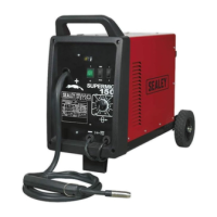
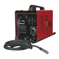
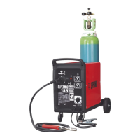
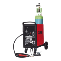
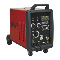
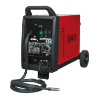
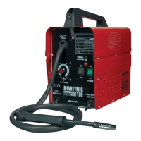
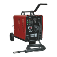
The SUPERMIG150.V4 is a MIG/MAG welder equipped with a forced air cooling system, allowing for a high duty cycle. It features a robust chassis designed to remain stable even with medium-sized industrial gas cylinders. The welder utilizes a professional contour grip, heat-proof non-live torch that prevents sparks until the trigger is pressed. Its proven wire feed system ensures trouble-free welding, making it suitable for welding stainless steel and aluminum.

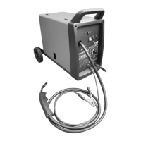
The welding process involves automatically feeding welding wire through an insulated liner to the torch tip. The torch, comprising a switch, liner, gas hose, and control cable, activates the wire feed roller and gas flow when the switch is pressed. Releasing the switch stops both wire feed and gas flow. The weld current is transferred to the electrode (the wire) from the contact tip at the torch end. The current to the electrode is set using two switches on the front control panel, while wire speed is adjusted via a rotary control below the power switches. Higher current settings require faster wire speed. A gas cup fits over the contact tip to direct gas flow towards the weld, shielding the arc welding process from oxidation and assisting in heating the weld. The torch is connected to the positive side of a DC rectifier, and the negative clamp is attached to the workpiece.

Important Technical Specifications

  • Model No.: SUPERMIG150.V4
  • Welding current: 30-150A
  • Wire Capacity: 0.7-5kg
  • Duty Cycle: 100% @ 47A, 60% @ 60A, 20% @ 105A
  • Cooling System: Forced Air
  • Spot Welding Timer: No
  • Gas Type: CO2, Argon, CO2/Argon Mix
  • Torch: 2m Non-Live
  • Supply: 230V
  • Absorbed Power: 4.37kW
  • Case Size: Compact
  • Insulation Class: H
  • Protection: IP21S

The rating plate on the front panel provides additional data:

  • BS/EU standard: Relates to the safety and construction of arc welding equipment.
  • Inverter-transformer-rectifier symbols: Indicates the type of power source.
  • Welding symbol: Indicates welding with a continuous flow of welding wire.
  • Single-phase AC supply symbol.
  • Internal protection rating: Provided by casing.
  • Output: U₀ (Maximum open-circuit voltage), I₂ (Current), U₂ (Corresponding voltage).
  • Welding ratio (X): Based on a 10-minute cycle (e.g., 20% indicates 2 minutes welding and 8 minutes rest).
  • Mains Supply: U₁ (Rated supply voltage and frequency), I₁max (Maximum current), I₁eff (Maximum effective current).
  • A/V: Welding current adjustment range and corresponding voltages.
  • Serial Number: Uniquely identifies each welder.
  • Welding power sources symbol: Indicates suitability for supplying power in environments with increased risk of electric shock.

Usage Features

Assembly:

  • Wheels: Slide the rear axle through loops on the underside of the rear tray, attach wheels with washers and split pins. Attach the front foot using screws.
  • Handle: Align the front half of the handle moulding with fixing holes on the welder's top surface and secure with bolts. Snap the rear part of the handle moulding into the front half and secure with self-tapping screws.

Connecting the Gas Cylinder:

  • Place the lower end of the gas cylinder on the rear tray.
  • Secure the cylinder by hooking either end of the chain through the metal support as shown in fig.2.
  • For CO2 gas, use the bull nose adaptor. For Argon or Argon mixtures, use the bull nose adaptor with a spanner.
  • Fit the gas regulator onto the bull nose adaptor.
  • Push the plastic tube provided onto the gas outlet nozzle on the regulator and retain it with the wire clip.
  • Push the other end of the tube onto the gas outlet nozzle on the welder and retain it with the other wire clip.
  • Set the gas flow rate between 5-8 litres/min depending on the material to be welded.

Fitting a Reel of Wire:

  • Place the wire reel onto the reel hub, ensuring the small hole in the side of the reel faces the wire feed unit.
  • Uncoil approximately 50cm of wire and trim the end.
  • Loosen the wire tension knob and move the tensioning roller assembly to its up position.
  • Take hold of the triangular knob on the roller retainer and rotate it 90° anticlockwise to release it.
  • Pull the roller retainer off the drive spindle to reveal the roller.
  • Feed the wire through the wire guide and over the feed roller.
  • Push the roller retainer back onto the drive spindle, ensuring the flanges at the base of the retainer seat fully into the circular recess in the main moulding.
  • Rotate the retainer through 90° to lock it in place.
  • Move the tensioning roller assembly to its down position and tighten the wire tension knob.

Feeding Wire Through the Torch:

  • Remove the gas cup and contact tip.
  • Straighten the torch cable.
  • Turn the welder on and set the wire speed control to 5 or 6.
  • Depress the torch switch and feed the wire through the torch.
  • When the wire has fed through, switch welder off, unplug from mains.
  • Replace the contact tip and gas cup.

Setting Wire Tension:

  • Correct tension is crucial for proper wire feed and weld quality.
  • For mild steel 0.6mm wire, fully tighten the wire tension screw and then undo it approximately two complete turns.
  • Check tension by slowing the wire between fingers; if the pressure roller skids, tension is correct.
  • Use the lowest possible tension to avoid deforming the wire and blowing a fuse.

Thermal Protection:

  • If the welder overheats due to prolonged use beyond its stated duty cycle, the thermal protection will activate, causing the welder to cut out and the amber light on the front panel to illuminate.
  • Allow 15 minutes for the welder to cool down before it automatically reconnects.

General Safety:

  • Always unplug the welder before maintenance or service.
  • Keep the welder and cables in good working order; repair or replace damaged parts immediately.
  • Use only genuine parts and accessories.
  • Regularly blow out dirt from the liner with an air hose and keep the welder clean.
  • Check and spray the gas cup and contact tip with anti-spatter spray.
  • Ensure adequate ventilation in the work area, which should be clean, tidy, and free from unrelated materials.
  • Always have a fire extinguisher at hand.
  • Wear a welding head shield, safety welding gauntlets, and remove ill-fitting clothing, ties, watches, rings, and loose jewelry. Contain long hair.
  • Ensure the workpiece is correctly secured.
  • Avoid unintentional contact with the workpiece.
  • Keep unauthorized persons away from the work area; those within the area must wear protective gear.
  • Operators must be adequately trained.
  • Stand correctly with good footing and balance on a non-slippery floor.
  • DO NOT operate if the welder or cables are damaged.
  • DO NOT get the welder wet or use in damp/wet locations.
  • DO NOT attempt to fit unapproved torches or components.
  • DANGER! DO NOT weld near flammable solids, liquids, or gases, or containers that have held flammable materials. Avoid welding materials cleaned with chlorinated solvents.
  • DO NOT stand the welder on a metal workbench, car bodywork, or similar.
  • DO NOT touch any live metal parts of the torch or electrode when the machine is switched on.
  • DO NOT pull the welder by the cable or torch. Protect cables from sharp or abrasive items. DO NOT bend, strain, stand on cables, or place them where they endanger others.
  • DO NOT touch the torch or workpiece immediately after welding.
  • DO NOT operate while under the influence of drugs, alcohol, or medication, or if tired.
  • Store the welder in a safe, dry, childproof area when not in use.

Gas Safety:

  • Store gas cylinders vertically and securely.
  • DO NOT store gas cylinders in areas where the temperature may exceed 50°C. DO NOT use direct heat on a cylinder.
  • DO NOT attempt to repair or modify any part of a gas cylinder or valve.
  • DO NOT puncture or damage a cylinder.
  • DO NOT obscure or remove any official labels.
  • Always check gas identity before use. Avoid getting gas cylinders oily or greasy.
  • DO NOT lift a cylinder by the cap, guard, or valve. Keep caps and guards in place and close the valve when not in use.

Maintenance Features

DANGER! Always unplug the welder from the mains power supply before performing maintenance or service.

Wire Feed Unit:

  • Check the wire feed unit at regular intervals.
  • Clean the rollers weekly, especially the feed roller groove, to remove dust deposits. Poor wire feed affects the weld.

Torch:

  • Protect the torch cable assembly from mechanical wear.
  • Clean the liner from the machine forwards using compressed air. Replace the liner if blocked.

Contact Tip:

  • The contact tip is a consumable item and must be replaced when the bore becomes enlarged or oval.
  • Keep the contact tip free from spatter to ensure unimpeded gas flow.

Gas Cup:

  • Keep the gas cup clean and free from spatter.
  • Spatter build-up inside the gas cup can cause a short circuit at the contact tip, leading to fuse blowing or expensive machine repairs.
  • Use anti-spatter spray (MIG/722307) to keep the contact tip free from spatter.

Turning Feed Roller:

  • The feed roller has two grooves (0.6mm and 0.8mm). Ensure the groove being used is on the outside of the roller (nearest to you).
  • To turn the feed roller: loosen the wire tension knob, move it to its down position, then move the tensioning roller assembly to its up position.
  • Rotate the triangular knob on the roller retainer 90° anticlockwise to release it.
  • Pull the roller retainer off the drive spindle to reveal the roller.
  • Pull the roller off the drive spindle, flip it over, and put it back on the drive spindle so the desired groove size is visible.
  • Push the roller retainer back onto the drive spindle, ensuring flanges seat fully into the circular recess in the main moulding, then rotate the retainer through 90° to lock it in place.

Replacing Wire Liner:

  • A worn or damaged wire liner will seriously affect welder performance and should be replaced immediately.
  • Wind the wire back onto the spool and secure it.
  • Remove the four screws securing the torch cable clamp to the wire feed unit and take off the clamp.
  • Undo the torch case and pull the wire liner from the insulation block.
  • Pull out the liner from the torch cable and insert the new one.
  • Reverse the process to re-assemble, ensuring the liner is fully inserted into the torch insulation block.
  • Trim the other end of the liner as close to the feed roller as possible.
  • Replace the torch cable clamp.

Replacing Gears:

  • Spatter build-up in the tip and shroud can block wire feed and damage gears in the wire drive.
  • To check for worn gears: depress the torch button with the set switched on. If a grating sound is heard from the wire feed motor or the feed roller vibrates, return the welder to a Sealey stockist for repair.

Troubleshooting: The manual provides a comprehensive troubleshooting guide for common problems, their possible causes, and recommended remedies. This includes issues such as:

  • Welding current interrupted (overheating, poor connection, break in earth lead).
  • Feed motor not working (motor defective, rollers improperly adjusted).
  • Wire does not feed, feed roller rotates (pressure roller slipping, gas cup/nozzle/tip defective).
  • Wire feeds unevenly (dirt, etc. in liner, gas cup/nozzle/tip defective, feed roller groove clogged).
  • Unstable arc (incorrect settings, impurities in weld area, gas cup/nozzle/tip defective).
  • Porous weld (gas cup clogged, draft blowing away shielding gas, gas leak, torch too far from workpiece, gas cup/nozzle/tip defective).
  • Wire sticking in gas cup/nozzle (wire deformed, incorrect wire tension).
  • Irregular weld bead (incorrect wire tension, incorrect wire feed, incorrect torch angle).
  • Weld bead too narrow and raised (weld current too low, weld speed too fast).
  • Weld bead too wide (weld current too high, weld speed too slow).
  • Poor penetration (weld current too low, arc too long).
  • Excessive penetration (weld current too high, weld speed too slow, incorrect distance of torch to workpiece).

Environmental Protection:

  • Dispose of the product at the end of its working life in compliance with the EU Directive on Waste Electrical and Electronic Equipment (WEEE).
  • Recycle unwanted materials instead of disposing of them as waste. All tools, accessories, and packaging should be sorted, taken to a recycling centre, and disposed of in an environmentally sound manner.
  • Return fluids to a local amenity site.

Warranty: Lifetime guarantee on Transformer - Comprises 1 year unconditional parts and labour on all parts, followed by a lifetime guarantee (parts and labour) conditional on registering your purchase with Sealey.

Sealey SUPERMIG150.V4 Specifications

General IconGeneral
BrandSealey
ModelSUPERMIG150.V4
CategoryWelding System
LanguageEnglish

Related product manuals