4.6. SETTING WIRE TENSION
IMPORTANT: You must set the correct tension, too little or too much tension will cause problematic wire feed and result in a poor weld.
4.6.1. For mild steel 0.6mm wire the wire tension screw must be fully tightened and undone approximately two complete turns (g.7).
4.6.2. Correct tension between the rollers is checked by slowing down the wire between the ngers. If the pressure roller skids the tension
is correct. Try to use the lowest tension possible as too high a tension will deform the wire and may result in blowing a fuse on the
printed circuit board. When you have completed welding disconnect the unit from the mains supply and store it in a safe, dry place.
Note: Damaged torches and cables are not covered under warranty.
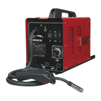
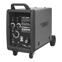
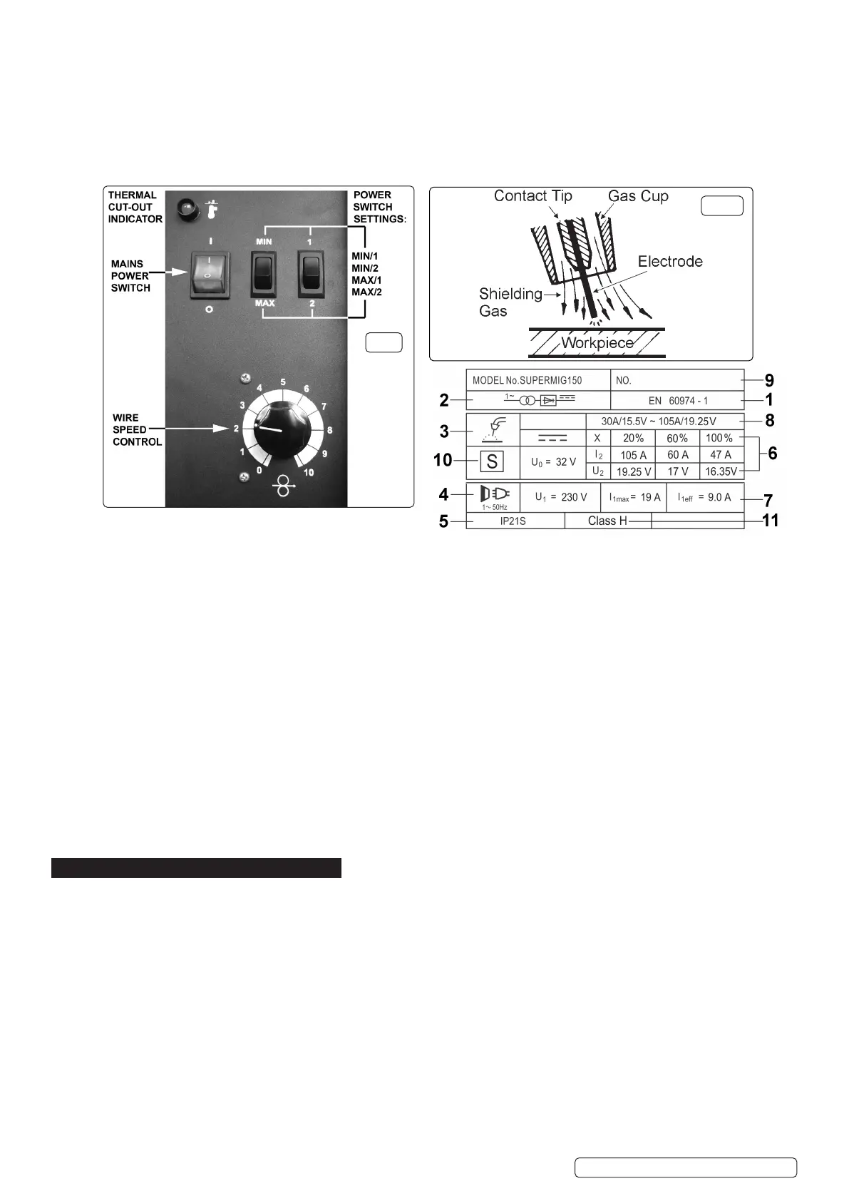
4.7. CONTROL PANEL FUNCTIONS
Refer to g.8 below.
4.8. MIG/MAG WELDING
4.8.1. Welding wire is automatically fed through an insulated liner to the tip of the torch. The torch consists of a switch, liner, gas hose, and
control cable. The switch activates the wire feed roller and the gas flow. Releasing the switch stops wire feed and gas flow. The weld
current is transferred to the electrode (the wire) from the contact tip at the torch end. The current to the electrode is set using the two
switches on the front of the control panel. Wire speed must be adjusted according to current output using the rotary control below the
power switches. The higher the current the faster the wire speed. A gas cup fits over the contact tip to direct gas flow towards the
weld, (See fig.9) ensuring that the arc welding process is shielded from oxidisation. The shielding gas also assists heating of
the weld. The torch is connected to the positive side of a DC rectifier, and the negative clamp is attached to the workpiece.
4.9. PREPARATION FOR WELDING: IMPORTANT! BEFORE YOU COMMENCE, MAKE SURE THE MACHINE IS SWITCHED OFF
AT THE MAINS. IF WELDING A VEHICLE, DISCONNECT THE BATTERY OR FIT AN ELECTRONIC CIRCUIT PROTECTOR. ENSURE
THAT YOU READ, UNDERSTAND AND APPLY THE SAFETY INSTRUCTIONS IN SECTION 1.
4.9.1. To ensure a complete circuit, the negative lead must be securely attached to the workpiece close to the weld area. Best connection is
obtained by grinding the point of contact on the workpiece before connecting the clamp.
4.9.2. The weld area must be free of paint, rust, grease, etc.
4.10. GAS TYPES AND THEIR USE
4.10.1. Welding mild steel with CO
²
gas is appropriate for most welding tasks where spatter and high build-up of weld do not pose a problem. To
achieve a spatter free and flat weld however, requires an Argon/CO
²
mixture.
4.10.2. To weld aluminium use: Argon Gas 0.8mm Contact Tip 0.8mm Aluminium Wire (MIG/2/KAL08).
4.11. THERMAL PROTECTION
Should the welder become overheated due to prolonged use beyond the stated duty cycle the thermal protection will cause the welder
to cut out and the amber light on the front panel will illuminate. Wait for fifteen minutes for the welder to cool down at which time it will
reconnect automatically.
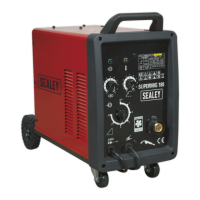
5. RATINGS PLATE (SEE ABOVE)r
On the front panel of the welder is the rating plate, giving the following data:
1 -The BS/EU standard relating to the safety and construction of arc welding and associated equipment.
2 - Inverter-transformer-rectifier symbols
3 - Symbol indicates welding with a continuous flow of welding wire.
4 - Symbol for Single-phase AC supply.
5 - Rating of internal protection provided by casing.
6 - Output
U
0
: Maximum open-circuit voltage.
I
2
, U
2
: Current and corresponding voltage.
X: Welding ratio based on a 10 minute cycle. 20% indicates 2 minutes welding and 8 minutes rest, 100% would indicates continuous
welding.
7 - Mains Supply U
1
: Rated supply voltage and frequency. I
1
max: Maximum current. I
1
eff: Maximum effective current.
8 - A/V - A/V: Welding current adjustment range and corresponding voltages.
9 - Serial Number. Specifically identifies each welder.
10- Symbol for welding power sources which are suitable for supplying power to welding operations carried out in an environment with
increased risk of electric shock (if applicable).
11- Insulation Class.
fig.8
fig.9
Original Language Version
© Jack Sealey Limited
SUPERMIG150.V4 Issue:1 08/07/22
 Loading...