253.872.0284 Page 6 seametrics.com
AG2000 INSTRUCTIONS
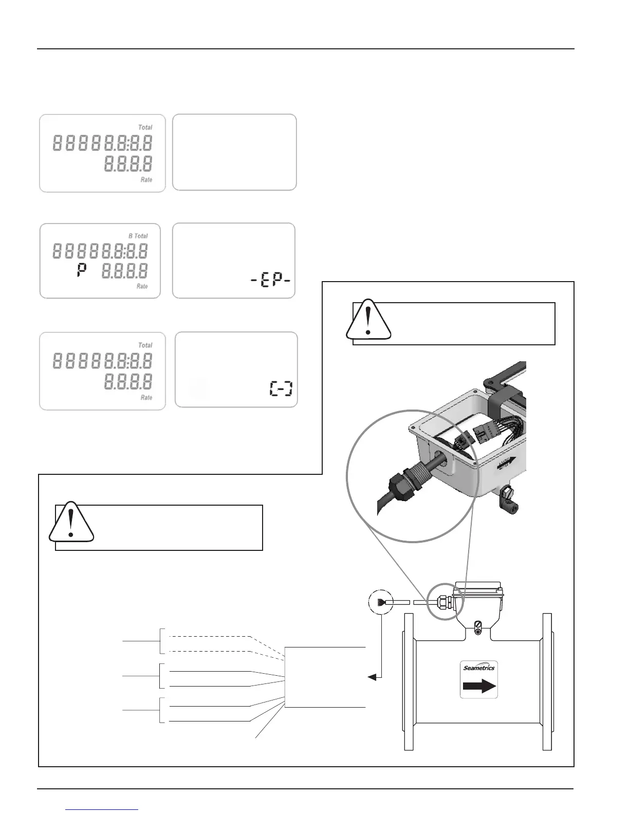
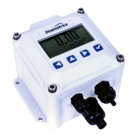
Low
Batt
Low Battery Indicator
External Power Indicator
Battery Power
Display Reading. There are two lines to the display, the
bottom line for ow rate and the top line for accumulated
total. Measurement units are pre-ordered and factory-set and
can be changed in the eld only by an authorized individual.
Empty Pipe
No Power
Meter Installed Backwards
Optional Input and Outputs. An optional cable, factory-
installed or field-installed by an authorized individual,
provides power input, pulse output* for remote reading (4-20
mA conversion, telemetry and data logging functions). See
diagram below. Detailed wiring diagrams provided with cable.
*See High Frequency Output Technical Bulletin for available
pulse rates.
For data logger setup and operation, refer to FlowInspector Manual
OPERATION
Optional Input/Output Cable - Factory or Field Installed
Not Currently Assigned
for Use.
External Power
Pulse Output
AG2000 Cable
Blue
Orange
Black (-)
Red (+)
Shielded
Direct Burial Cable
22 AWG Stranded
White (-)
Green (+)
Drain Wire
FLOW
800.975.8153
Orange and Blue: Serial Output (Technician Use Only)
Green (+) and White (-): Pulse Output, 30 Vdc max, 10 mA max
Red (+) and Black (-): External Power, 8-32 Vdc at 30 mA max (See WARNING)
Drain: Connect to earth ground
WARNING: Using an unregulated power
supply >18 Vdc may damage the meter
due to AC line input voltage uctuation.
IMPORTANT: Ensure that plastic cable
gland is sealed with tape or sealant
and that cap is tight.