

J
Joshua WashingtonAug 14, 2025
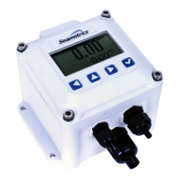
What to do if my Seametrics iMAG 4700r Measuring Instruments display is blank?
- AAdam MosleyAug 14, 2025
If your Seametrics Measuring Instruments display is blank, it could be due to several reasons: * Check the wiring from the power source to the meter for any incorrect connections. Use a DMM to measure the voltage at the terminal block TB1 on the back of the display, ensuring correct polarity and a steady voltage between 9Vdc and 32Vdc. * Ensure the backup battery is properly plugged in. * If the battery is plugged in, it may be dead and require replacement.