IMAG 4700r INSTRUCTIONS
Seametrics • 253.872.0284 Page 11 seametrics.com
CONNECTIONS
General Cable Information
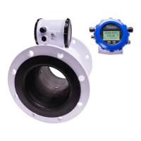
For the iMAG 4700r, a cable needs to be installed from the
terminal block on the remote display interface board to the
15 pin connector inside the remote display. This cable is
referred to as the remote meter cable. Four wires need to
be connected: +REM PWR, - REM PWR, B, and A. There
are an additional 2 cable ports that can be used for power
(DC or AC) and any outputs that are installed on the meter
such as scaled pulse, 4-20mA, and Modbus
®
. (See Sample
Control Cable Wiring Diagrams and Control Cable Wiring
Table.)
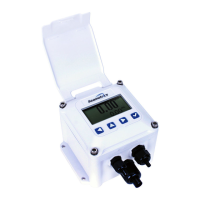
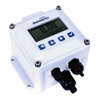
Remote Meter
Remote Meter
Cable
Remote Display
Power/
Output
Cable 2
Power/
Output
Cable 1
Cable Gland Opening and Sealing
The display is available in either DC or AC versions.
DCversionACVersion
If the meter is congured with AC power, one of the
additional Power/Output cable ports must be reserved
for AC power only. We do not recommend combining AC
power signals with any of the meter outputs in a single
cable. If the meter is congured for DC power, you may
have one or two cables, depending on conguration. (See
Cable Wiring Diagrams.)
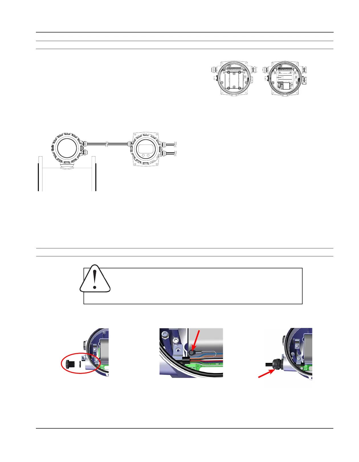
Clampcablewithstrainrelief
clips.Attachdrainwirelugto
bracket post.
Removeplug&o-ring.Insert
cable gland/strain relief. Feed
cable through cable gland.
CRITICAL!
Torquecableglandsealing
nutto22in-lbs.
NOTICE: Improper sealing of glands or cables will invalidate any warranty.
If plugs or cable glands are removed, reinstall using Teon pipe sealant, or tape, to ensure maximum
moisture protection.
AVIS: Une mauvaise étanchéité des presse-étoupes ou des câbles annulera toute garantie.
Si les bouchons ou les presse-étoupes sont retirés, réinstallez-les à l’aide d’un scellant pour tuyaux en
Téon ou d’un ruban adhésif pour assurer une protection maximale contre l’humidité.
 Loading...