IMAG 4700r INSTRUCTIONS
Seametrics • 253.872.0284 Page 12 seametrics.com
CONNECTIONS
Remote Display Wiring
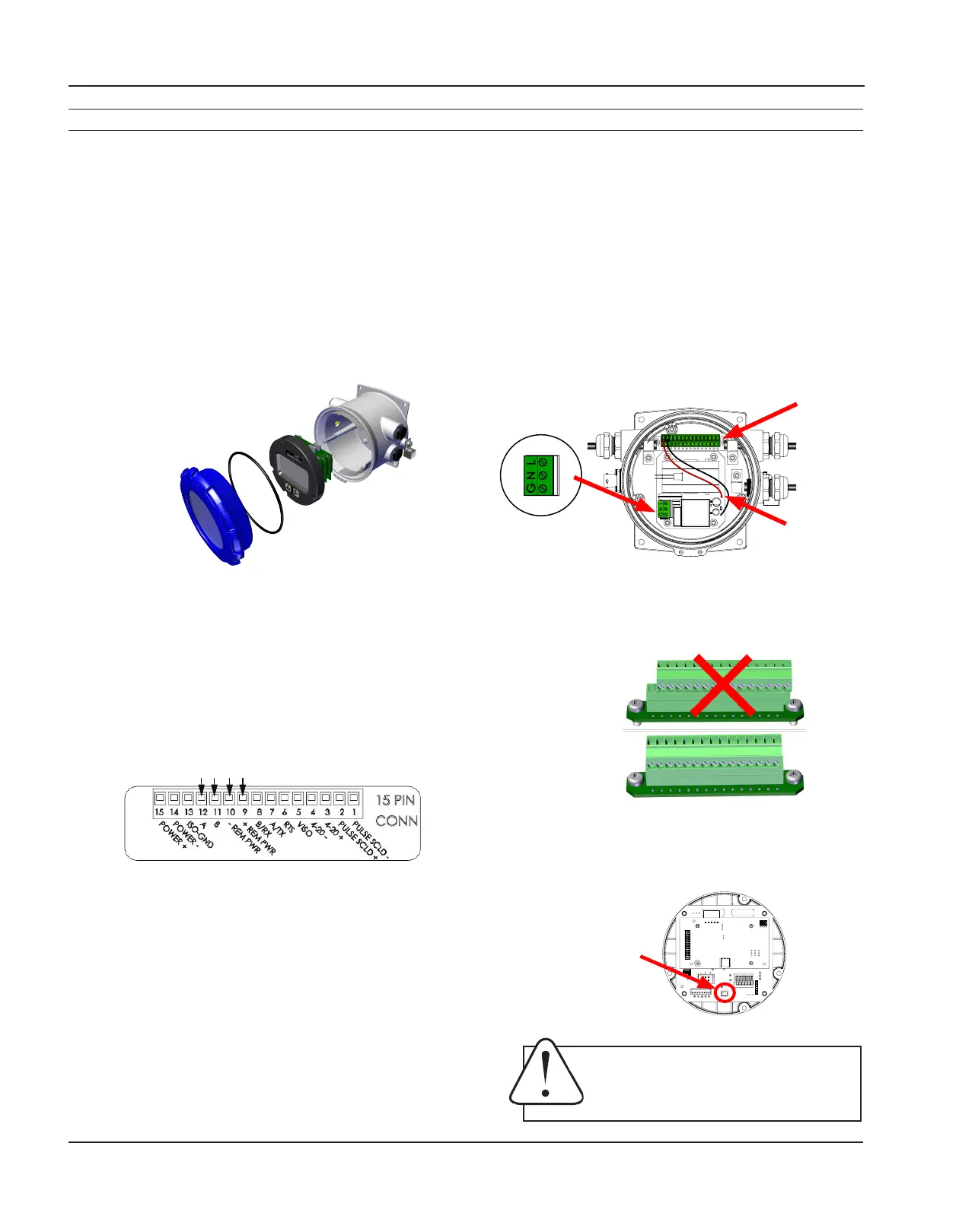
1. On the remote display, unscrew the display lid and
remove it.
2. The display assembly is held in with 3 fasteners.
If those fasteners are steel screws (silver) remove
them with a T-15 Torx driver and lift the diplay out
of the meter. If the fasteners are white Nylon tabs
with exposed straight slots, simply grasp the two
nger recesses in the display, then pop the diplay
up and out of the housing.
This will expose the internal 15 pin connector. Be
sure NOT to undo any connections to the display
assembly as you remove it.
3. Remove the 15 pin screw connector from the bag.
4. Remove the plug and o-ring from the cable port(s)
where you want to insert the cable(s).
5. Install cable gland(s) using Teon pipe sealant, or tape,
and insert cable end(s).
6. Strip cable jacket and conductors and install the
wires into the screw connector in their respective
locations (+REM PWR
(
red),
-
REM PWR (black), B
(orange), and A (blue)).
7. At this point, install any other options (Modbus
®
,
pulse, etc…) using the Power/Output cable(s)
through the Power /Output cable port(s), and
securely screw them into the screw connector in
their respective locations. (See Cable Wiring Table
for details.)
8. If using AC power version continue here. If not, then
skip to step 13. If AC then take the red and black
wires coming out of the AC supply board and install
in POWER+ and POWER
-
(red wire to pin 15, black
wire to pin 14).
9. When the AC power supply board is installed, 85-
264 VAC power is supplied via a 3 conductor power
cord. If installed outdoors or less than 33ft. (10m)
from a utility power service entrance, AC power
should be supplied via a properly-grounded surge
suppression device.
10. Remove the plug and o-ring from the AC cable
port.
11. Install cable gland and insert cable end.
12. Strip cable jacket and conductors and install 3
conductor power cable and wire to Line (L), Neutral
(N) and ground (G) positions on power supply
terminal block.
13. Plug the 15 pin screw connector into its socket.
Be sure all pins align properly and that the
connector has not slipped to one side.
14. Plug the backup battery cable into the back of
the display assembly. (Standard backup batteries
are two 3.6V “D” lithium cells. For the AC option, the
backup battery is a 9V alkaline cell.)
Internal
ACwires
15pin
connector
Power
supplyterminal
block(ACversions)
Backup
battery
connection
Cable Installation
Improper
alignment
Proper
alignment
NOTICE: BACKUP BATTERIES ARE NOT INTENDED AS A PRIMARY
POWER SOURCE OF A MAINS (DC or AC) CONFIGURED METER.
AVIS: LES PILES DE SECOURS NE SONT PAS CONÇUES COMME
SOURCE D’ALIMENTATION PRINCIPALE D’UN COMPTEUR
CONFIGURÉ SUR SECTEUR (CC ou CA).

 Loading...