IMAG 4700r INSTRUCTIONS
Seametrics • 253.872.0284 Page 13 seametrics.com
CONNECTIONS
15. Secure the cables inside the internal strain relief
clips and tighten the cable gland sealing nuts
securely (torque nut to 22 in-lbs). A loose nut
could cause moisture ingress and compromise the
meter head’s IP68 rating, voiding the warranty.
16. Remount the display assembly, being careful to not
pinch any wires, and install the display assembly
screws.
17. Reinstall the display lid, being sure to avoid cross-
threading the lid.
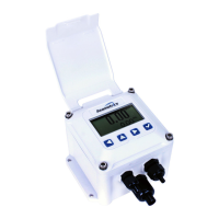
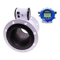
Remote Meter Wiring
1. On the remote meter, unscrew the user access lid
and remove it.
2. Remove the 5 pin screw connector from its socket.
3. Remove the plug and o-ring from the cable port.
4. Install cable gland and insert cable end.
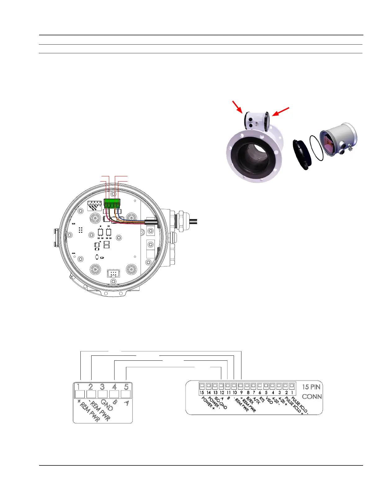
5. Strip cable jacket and conductors and install
the wires into the 5 pin screw connector in their
respective locations (+REM PWR
(
red),
-
REM PWR
(black), B (orange), and A (blue)).
6. Secure the remote sensor cable inside the internal
strain relief clip and tighten the cable gland sealing
nut securely (torque nut to 22 in-lbs.). A lose nut
could cause moisture ingress and compromise the
meter head’s IP68 rating; voiding the warranty. Plug
the 5 pin screw connector into its socket.
7. Reinstall the user access lid. Be sure to avoid cross-
threading the lid and to not pinch any wires with
the lid.
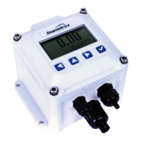
User access lid Front panel—
do not open
RED
BLACK
ORANGE
BLUE
Remotemeter15pinconnectorinremotedisplay
Orange (R) Remote B: pn4
Blue (R) Remote A: pn5
R
Black (R) -Remote Pwr: pn2
Red (R) +Remote Pwr: pn1
Remote Meter
Cable Installation (continued)
 Loading...