IMAG 4700r INSTRUCTIONS
Seametrics • 253.872.0284 Page 15 seametrics.com
CONNECTIONS
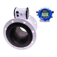
Wiring Diagrams (Remote Display) (continued)
The display assembly is held in with 3 fasteners. If those fasteners are steel screws (silver) remove them with a T-15
Torx driver and lift the diplay out of the meter. If the fasteners are white Nylon tabs with exposed straight slots, simply
grasp the two nger recesses in the display, then pop the diplay up and out of the housing. Remove the 15 pin screw
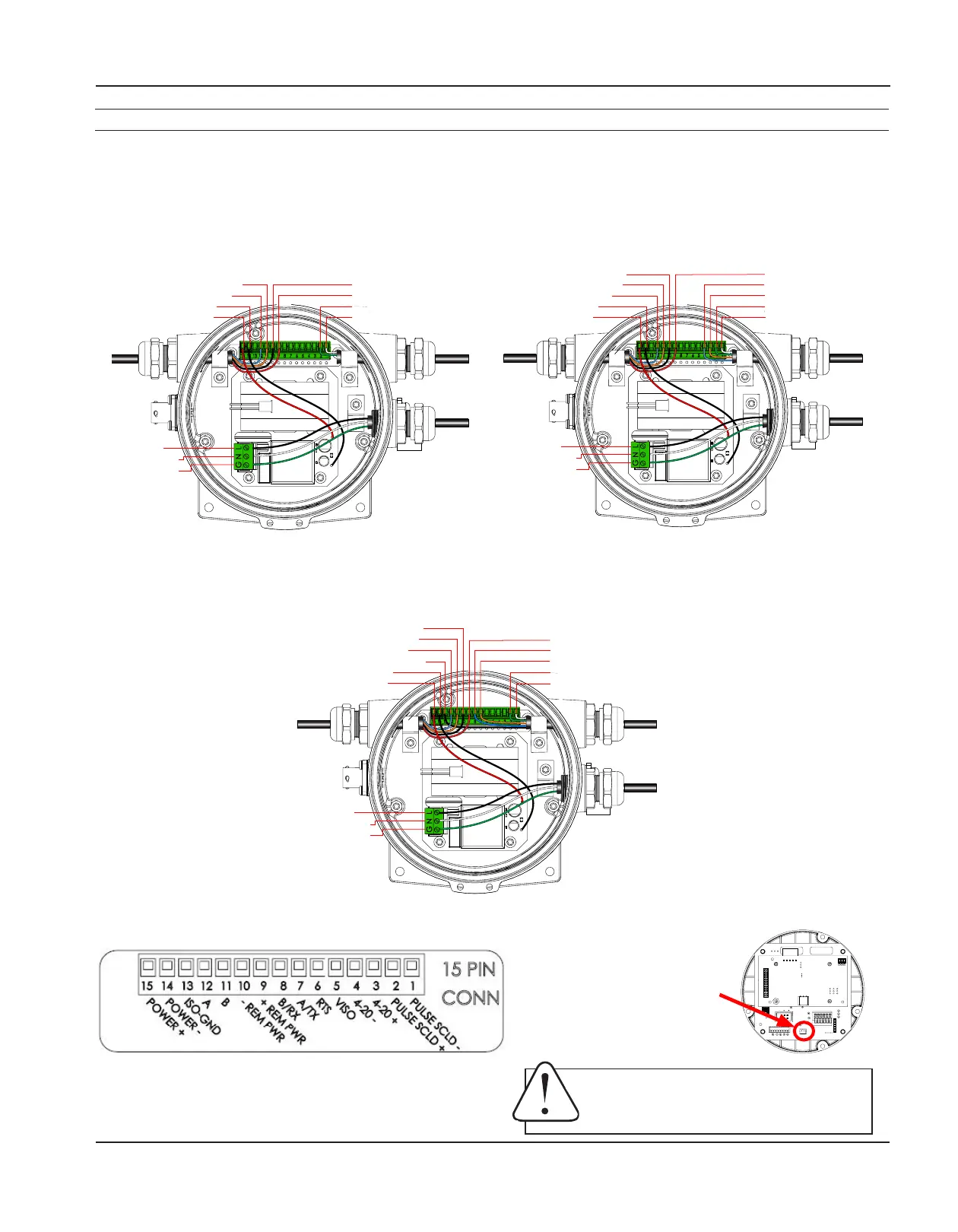
connector from its bag. Install the wires through the cable glands into the 15 pin screw connector in their respective
locations. Plug the 15 pin screw connector into its socket. (C1=power/outputcable,R=remotecable,AC=ACpower
cable)
AC Power with Pulse and 4-20mA (A1L/A2L)AC Power with Pulse (A1X/A2X)
AC Power with Pulse and Modbus
®
(A1S/A2S)
Plug the backup battery
cable into the back of the
display assembly.
Black (Line)
White (Neutral)
Green (Ground)
Black (R) -Remote Pwr: pn10
Red (R) +Remote Pwr: pn9
Green (C1) Pulse+: pn2
White (C1) Pulse-: pn1
Orange (R) Remote B: pn11
Blue (R) Remote A: pn12
Black (Internal): pn14
Red (Internal): pn15
C1
R
AC
Black (Line)
White (Neutral)
Green (Ground)
Red (R) +Remote Pwr: pn9
Blue (C1) 4-20mA: pn4
Orange (C1) 4-20mA+: pn3
Green (C1) Pulse+: pn2
White (C1) Pulse-: pn1
Black (R) -Remote Pwr: pn10
Orange (R) Remote B: pn11
Blue (R) Remote A: pn12
Black (Internal): pn14
Red (Internal): pn15
C1
R
AC
Black (Line)
White (Neutral)
Green (Ground)
Red (R) +Remote Pwr: pn9
Blue (C1) Modbus B/RX: pn8
Orange (C1) Modbus A/RX: pn7
Green (C1) Pulse+: pn2
White (C1) Pulse-: pn1
Black (R) -Remote Pwr: pn10
Orange (R) Remote B: pn11
Blue (R) Remote A: pn12
Black C1) Modbus Gnd: pn13
Black (Internal): pn14
Red (Internal): pn15
C1
R
AC
NOTICE: BACKUP BATTERIES ARE NOT INTENDED AS A PRIMARY
POWER SOURCE OF A MAINS (DC or AC) CONFIGURED METER.
AVIS: LES PILES DE SECOURS NE SONT PAS CONÇUES COMME SOURCE
D’ALIMENTATION PRINCIPALE D’UN COMPTEUR CONFIGURÉ SUR
SECTEUR (CC ou CA).
 Loading...