Searey LSA – Pilot’s Operating Handbook Version 5.0, Revision 8
51
7.3 FLIGHT CONTROLS
This section details the aircraft’s flight controls and control surfaces. All
control surfaces are constructed from aluminum tube and covered with
Poly-Fiber fabric. The control surfaces are assembled by bolting and/or
riveting aluminum tubes together using AN hardware. In several locations,
the tubes are separated and supported by using plastic saddles and/or
spacers at joints. The control surfaces all have similar hinges. These are
small stainless steel ‘U’ brackets that are bolted to the surfaces to be
hinged.
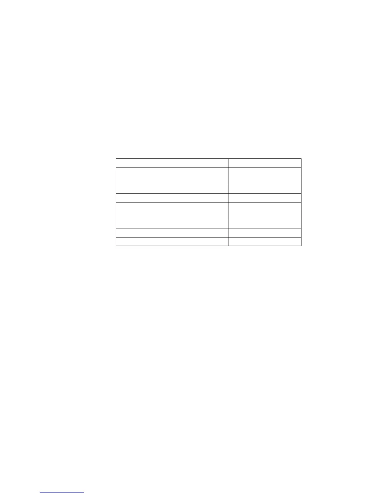
7.3.1 FLIGHT CONTROLS – SURFACE DEFLECTIONS
The control surface deflections are as follows:
Flaps - Neutral Flap Position
Flaps - First Flap Position
Flaps - Second Flap Position
Flaps - Third Flap Position
Flaps - Neutral Flap Position
Flaps - First Flap Position
Flaps - Second Flap Position
Note: All control surface deflection tolerances are +/- 2.
7.3.2 WING FLAPS
The electric flaps are actuated by an actuator that is located above the
pilot’s right shoulder. This lever actuates the flaps by a pushrod system.
A single pushrod connects the lever to an idler near the rear wing spar
attachment. This idler is then connected to the flaps by two pushrods,
one to each side of the fuselage. The idler acts as an interconnection
between the flaps.
Extension of the wing flaps is achieved by using the electric flap controller
located on the center console.
7.3.3 AILERONS
The aileron system is a combination of a bell crank, torque tubes and
seven push-pull rods.
A push rod runs from the lower end of each control stick to a central bell
crank, located under and between the two seats. A rod connects this
forward bell crank to a second rear bell crank which in turn connects to a