TESTING
Kenmore Elite 2013 Stainless Steel Tall Tub Dishwasher
n
5-19
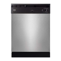
Strip Circuit – Lower Spray Arm Sensor
For Service Technician Use Only
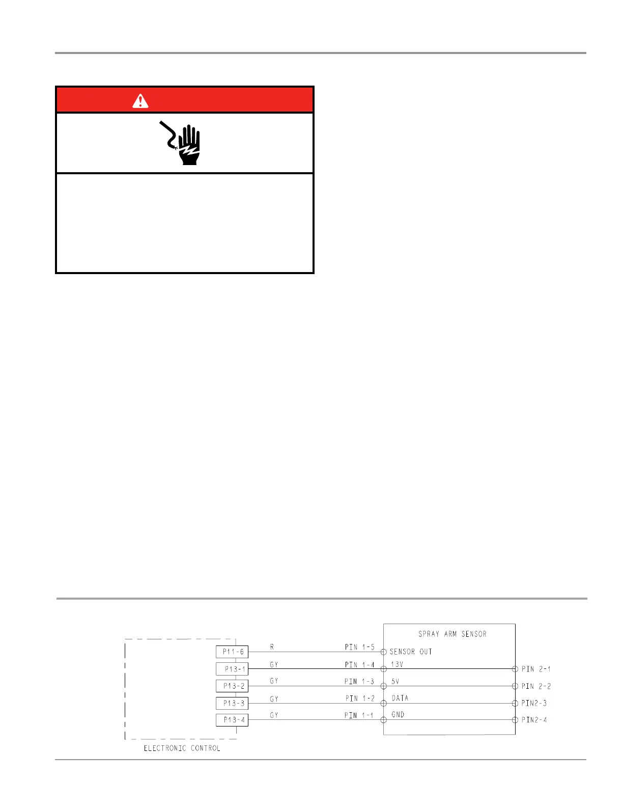
DANGER
Electrical Shock Hazard
Only authorized technicians should perform
diagnostic voltage measurements.
After performing voltage measurements,
disconnect power before servicing.
Failure to follow these instructions can result in
death or electrical shock.
Lower Spray Arm Sensor
This test will check the wiring to the spray arm sensor and the
sensor itself. The following items are part of the lower spray
arm sensor circuit.
■ Harness/Connecon
■ Lower Spray Arm Motor
■ Lower Spray Arm Sensor
■ Control Board
Test Procedure
1. Check for and remove anything blocking the lower spray
arm (utensils, pot handles, etc). Verify that the lters are
installed properly and not impeding spray arm rotaon.
Also, check for clogged spray nozzles and clean as needed.
2. Perform the Service Diagnosc Cycle to check status of
lower spray arm and sensor. The following operaons are
performed during “Interval 10” (4 minute lower wash).
Minute 1: LSA Rotates CCW
Minute 2: LSA Rotates CW
Minute 3: LSA Rotates CCW
¾ Clean LED lit to indicate LSA motor status good.
Minute 4: LSA Rotates CW
¾ Clean LED lit to indicate LSA sensor status good.
The following steps assume that this step was unsuccessful.
3. Unplug dishwasher or disconnect power.
4. Remove access panel and outer door panel.
5. Visually check that the spray arm sensor connector, P11
and P13 connectors on the control are securely installed.
¾ If visual check passes, go to step 6.
¾ If any of the connectors are not inserted properly,
reconnect and retest spray arm sensor.
6. Check connuity of harness between P11 and spray arm
sensor and P13 and spray arm sensor.
¾ If connuity test is good, connue to step 7.
¾ If connuity test fails, repair or replace harness as
needed.
7. With a voltmeter set to DC, connect the black lead to P13-
4 and the red lead to P13-2.
8. Plug in dishwasher or reconnect power.
9. Start the Diagnosc Cycle and during Interval 10, measure
for +5V DC out of the control between P13, pins 4 and 2.
¾ If +5V DC is measured, the control is funconing,
replace the spray arm sensor.
¾ If no DC voltage is measured, replace the control
board.
10. Perform Diagnosc Cycle to verify repair.
11. Reassemble all parts and panels.
12. Plug in dishwasher or reconnect power.