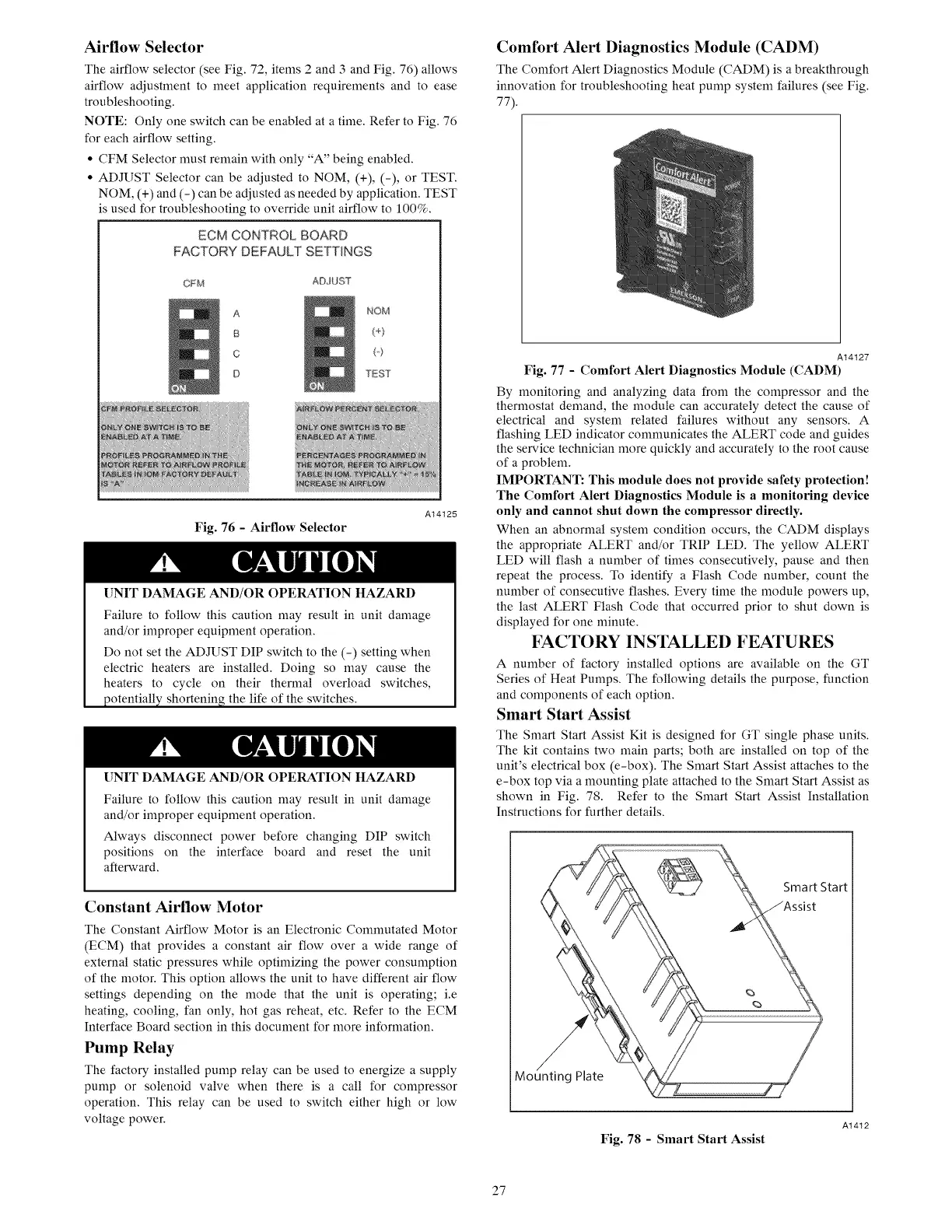
Airflow Selector
The airflow selector (see Fig. 72, items 2 and 3 and Fig. 76) allows
airflow adjustment to meet application requirements and to ease
troubleshooting.
NOTE: Only one switch can be enabled at a time. Refer to Fig. 76
for each airflow setting.
• CFM Selector must remain with only "A" being enabled.
• ADJUST Selector can be adjusted to NOM, (+), (-), or TEST.
NOM, (+) and (-) can be adjusted as needed by application. TEST
is used for troubleshooting to override unit airflow to 100%.
ECM CONTROL BOARD
FACTORY DEFAUU SETTINGS
CFM
ADJUST
A
B
C
D
NOM
(+)
(o)
TEST
Fig. 76 - Airflow Selector
A14125
UNIT DAMAGE AND/OR OPERATION HAZARD
Failure to follow this caution may result in unit damage
and/or improper equipment operation.
Do not set the ADJUST DIP switch to the (-) setting when
electric heaters are installed. Doing so may cause the
heaters to cycle on their thermal overload switches,
potentially shortening the life of the switches.
UNIT DAMAGE AND/OR OPERATION HAZARD
Failure to follow this caution may result in unit damage
and/or improper equipment operation.
Always disconnect power before changing DIP switch
positions on the interface board and reset the unit
afterward.
Constant Airflow Motor
The Constant Airflow Motor is an Electronic Conmmtated Motor
(ECM) that provides a constant air flow over a wide range of
external static pressures while optinfizing the power consumption
of the motor. This option allows the unit to have different air flow
settings depending on the mode that the unit is operating; i.e
heating, cooling, fan only, hot gas reheat, etc. Refer to the ECM
Interface Board section in this document for more information.
Pump Relay
The factory installed pump relay can be used to energize a supply
pump or solenoid valve when there is a call for compressor
operation. This relay can be used to switch either high or low
voltage power.
Comfort Alert Diagnostics Module (CADM)
The Comfort Alert Diagnostics Module (CADM) is a breakthrough
innovation for troubleshooting heat pump system failures (see Fig.
77).
A14127
Fig. 77 - Comfort Alert Diagnostics Module (CADM)
By monitoring and analyzing data from the compressor and the
thermostat demand, the module can accurately detect the cause of
electrical and system related failures without any sensors. A
flashing LED indicator conmmnicates the ALERT code and guides
the service technician more quickly and accurately to the root cause
of a problem.
IMPORTANT: This module does not provide safety protection!
The Comfort Alert Diagnostics Module is a monitoring device
only and cannot shut down the compressor directly.
When an abnormal system condition occurs, the CADM displays
the appropriate ALERT and/or TRIP LED. The yellow ALERT
LED will flash a number of times consecutively, pause and then
repeat the process. To identify a Flash Code number, count the
number of consecutive flashes. Every time the module powers up,
the last ALERT Flash Code that occurred prior to shut down is
displayed for one nfinute.
FACTORY INSTALLED FEATURES
A number of factory installed options are available on the GT
Series of Heat Pumps. The following details the purpose, function
and components of each option.
Smart Start Assist
The Smart Start Assist Kit is designed for GT single phase units.
The kit contains two main parts; both are installed on top of the
unit's electrical box (e-box). The Smart Start Assist attaches to the
e-box top via a mounting plate attached to the Smart Start Assist as
shown in Fig. 78. Refer to the Smart Start Assist Installation
Instructions for further details.
Smart Start
Mounting Plate
Fig. 78 - Smart Start Assist
A1412
27
 Loading...