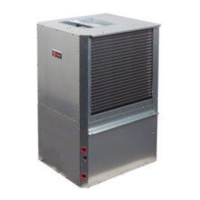
Installation Instructions
NOTE: Read the entire instruction manual before starting the installation,
TABLE OF CONTENTS
PAGE NO.
SAFETY CONSIDERATIONS ...................................................................... 2
APPLICATION CONSIDERATIONS ................................................................. 3
Geothermal Systems .......................................................................... 3
Well Water Systems ........................................................................... 4
INSTALLATION RECOMMENDATIONS ............................................................ 6
CONFIGURATIONS ............................................................................... 6
Horizontal Configuration ...................................................................... 6
Counter-Flow Configuration ................................................................... 12
Vertical Configuration ......................................................................... 12
MOUNTING VERTICAL UNITS .................................................................... 20
MOUNTING HORIZONTAL UNITS ................................................................. 20
CONDENSATE DRAIN ............................................................................. 20
DUCT SYSTEM ................................................................................... 20
PIPING .......................................................................................... 21
ELECTRICAL .................................................................................... 21
Safety Devices and UPM Controller .............................................................. 22
ECM Interface Board ......................................................................... 25
FACTORY INSTALLED FEATURES ................................................................. 27
Constant Airflow Motor ....................................................................... 27
Smart Start Assist ............................................................................ 27
Pump Relay ................................................................................ 27
Comfort Alert Diagnostics Module (CADM) ....................................................... 27
Heat Recovery Package (HRP) .................................................................. 28
FIELD INSTALLED ACCESSORIES ................................................................. 29
SEQUENCE OF OPERATION ....................................................................... 30
Cooling Mode ............................................................................... 30
Heating Mode ............................................................................... 30
ELECTRONIC THERMOSTAT INSTALLATION ...................................................... 30
SYSTEM CHECKOUT ............................................................................. 31
UNIT START-UP .................................................................................. 31
MAINTENANCE .................................................................................. 31
TROUBLESHOOTING ............................................................................. 32
OPERATING TEMPERATURES AND PRESSURES TABLES ............................................ 36
AIRFLOW TABLES ............................................................................... 40
WATER SIDE PRESSURE DROP TABLE ............................................................. 42
SMART START LED INDICATORS .................................................................. 43